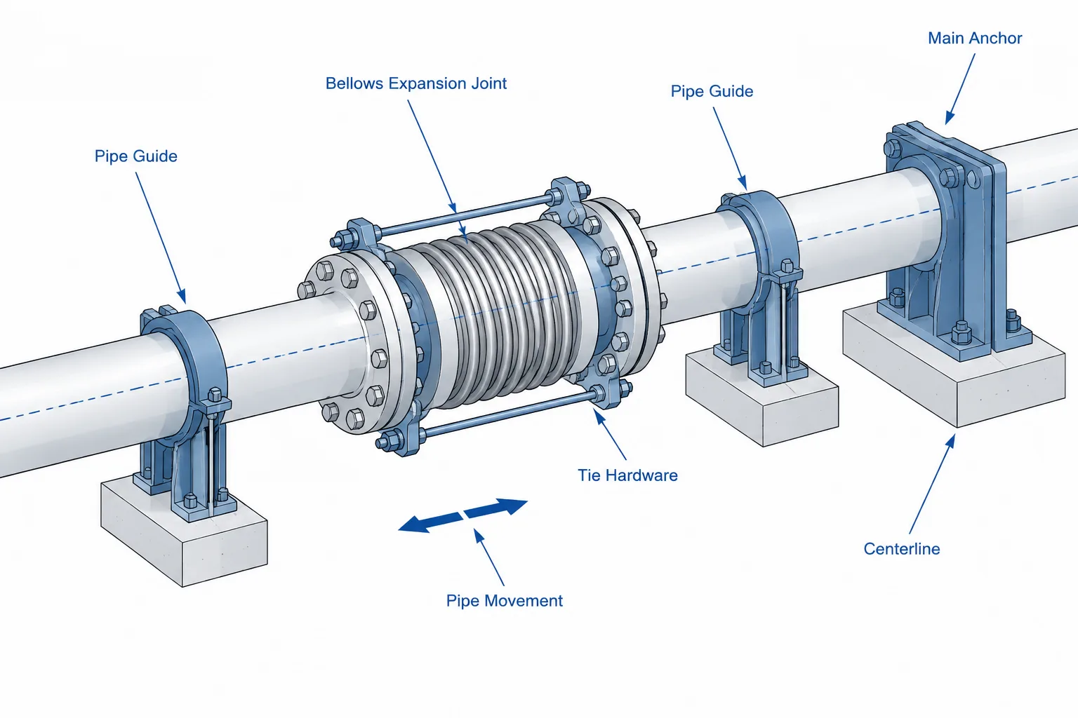
Metal bellows expansion joints in piping CAD must communicate more than component shape. The model should preserve the intended movement axis, connection geometry, orientation, external envelope, and relationship to the surrounding restraint system.
This reference explains how to represent these assemblies without treating visible flexibility as verified performance. Use controlled vendor and engineering documents for movement limits, loads, installed conditions, hardware functions, and final fabrication information.
A metal bellows expansion joint is not simply a flexible section of pipe. It is an engineered assembly intended to accommodate specified movement while operating within defined limits. Its behavior depends on the bellows configuration, end connections, internal hardware, external restraints, piping anchors, guides, and the loads applied by the connected system.
For CAD designers, the main challenge is translating that engineered behavior into geometry and documentation without implying capabilities that have not been verified. A generic flexible-looking component may be adequate during an early routing study, but fabrication and installation drawings require vendor-specific dimensions, movement data, orientation information, and restraint details.
What a metal bellows expansion joint does
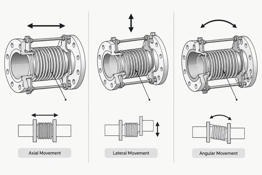
The bellows is a formed metallic element that can deform through controlled convolution movement. Depending on the assembly design, the joint may accommodate axial movement, lateral movement, angular rotation, or a defined combination of these motions.
The permitted movement is not determined by appearance alone. Two assemblies with similar overall shapes may have different bellows construction, hardware, pressure capability, spring behavior, and movement limits. CAD geometry should therefore be treated as a representation of a selected component, not as proof of its engineering performance.
Movement directions to identify before modeling
Every expansion joint should be associated with a local axis. This is normally the centerline running between its piping connections. Movement descriptions are interpreted relative to that axis.
| Movement term | Practical meaning | CAD implication |
|---|---|---|
| Axial | Compression or extension along the joint centerline | Show the correct installed face-to-face length and identify the movement direction where needed |
| Lateral | Transverse displacement between the two ends | Preserve the required offset direction and surrounding movement envelope |
| Angular | Rotation between the end axes | Model hinge or rotational axes accurately and avoid unintended restraint |
| Torsional | Twisting about the pipe centerline | Do not assume it is acceptable; bellows assemblies are generally not intended to absorb uncontrolled pipe torque |
A useful model attribute set includes the joint axis, intended movement type, movement direction, installed length basis, component tag, and reference to the controlling vendor or engineering document. These properties help reviewers distinguish purposeful flexibility from a modeling gap.
Common assembly configurations
Single bellows assembly
A single assembly contains one bellows element between its ends. It may be selected for axial, lateral, or angular behavior depending on the complete piping arrangement and its restraints. A single bellows should not automatically be modeled as a universal joint capable of movement in every direction.
Universal expansion joint
A universal arrangement uses two bellows separated by an intermediate pipe section. This configuration can accommodate lateral displacement through angular movement of the two bellows. The center section and any external tie hardware are important parts of the geometry, especially when checking nearby structures and access.
Hinged expansion joint
A hinged assembly includes hardware that controls movement around a defined rotational axis. The hinge orientation is therefore a functional requirement, not a cosmetic modeling choice. Rotating the component around the pipe centerline can change how the assembly behaves within the piping system.
Gimbal expansion joint
A gimbal assembly permits angular rotation about more than one controlled axis while restraining other movement. Its external framework can occupy substantial space beyond the pipe envelope and must be included in coordination models.
Pressure-balanced arrangement
A pressure-balanced system uses additional bellows and structural elements to manage pressure-induced forces within the assembly. These components can be geometrically complex. Simplification may be appropriate in an early model, but connection locations, envelope, orientation, and support interfaces still need to reflect verified information.
Why pressure thrust matters to the layout
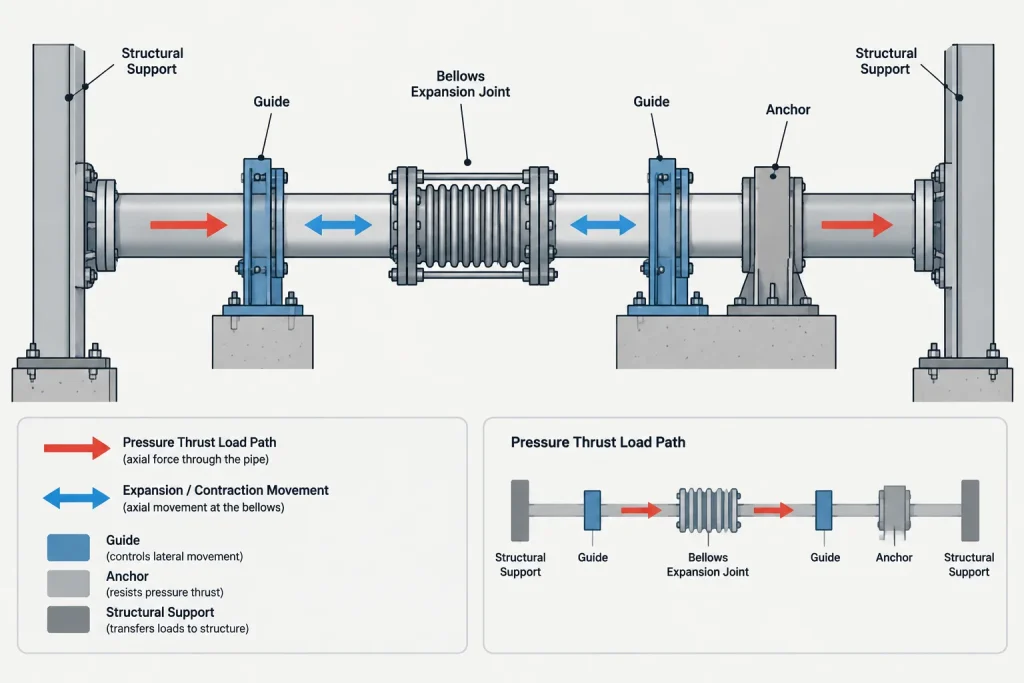
Internal pressure acting across an effective bellows area can create a longitudinal force commonly described as pressure thrust. An unrestrained expansion joint does not automatically contain this force merely because it is installed between two pipe ends.
The resulting loads may need to be resisted by main anchors, restrained joint hardware, equipment interfaces, or another engineered arrangement. The correct load path is a piping flexibility and mechanical design issue. A CAD designer should not add an expansion joint as a convenient solution to a routing problem without confirming the intended anchor and guide concept.
In the model and drawings, review the relationship among:
- The expansion joint and its intended movement axis
- Main and intermediate anchors
- Pipe guides and line stops
- Equipment nozzles and their allowable loads
- Branch connections near the flexible section
- Support locations and possible friction effects
- Structural steel receiving anchor or guide loads
If these elements are shown on separate discipline drawings, the interface should still be traceable through tags, coordinates, support references, or documented design notes.
Installed length, neutral length, and preset
The modeled face-to-face length must have a defined basis. Depending on the design, the installation length may correspond to a neutral condition, a specified cold condition, or a preset position intended to reserve movement in one direction.
Presetting changes the relationship between the supplied assembly and its installed condition. The drawing should not communicate preset by visually stretching or compressing an unverified generic bellows model. Instead, use the confirmed installation dimension and a clear note or data field identifying the controlling condition.
Temperature at installation may also affect the required setting. Because field conditions vary, installation instructions should come from the responsible engineering or vendor documentation rather than an assumption embedded only in CAD geometry.
Shipping bars, tie rods, and control hardware
External rods and brackets can serve different purposes. Some hardware is temporary and holds the assembly at a defined length during transport and installation. Other hardware is a permanent functional part of the expansion joint. Similar-looking rods should not be labeled solely from their appearance.
Temporary shipping devices require a clear removal or release instruction when applicable. Permanent rods, hinges, gimbals, or limit hardware must remain represented in the operating configuration. If the CAD model omits these items for performance reasons, the component should still carry enough metadata to prevent reviewers from interpreting the simplified body incorrectly.
Modeling the expansion joint at the right level of detail
A practical model should include enough geometry for routing, interference review, drawing extraction, and installation coordination. It usually does not need every bellows convolution unless detailed geometry serves a specific fabrication or visualization purpose.
Useful geometry commonly includes:
- Accurate connection locations and face-to-face length
- End type and connection orientation
- Maximum external body envelope
- Tie rods, hinges, gimbals, covers, or other projecting hardware
- Flow direction when the assembly or internal liner is directional
- Local movement or hinge axis
- Required access and movement clearance envelope
- Drain, vent, or monitoring connections when supplied
A simplified bellows symbol can identify the component, but the clash envelope should account for external hardware and expected motion. Checking only the cold static body may miss an interference that occurs as the piping moves.
Internal liners, covers, and orientation
An internal liner may be used to protect the bellows from flow effects or process material. Its arrangement can make the assembly directional. The CAD component should preserve any confirmed inlet and outlet orientation rather than allowing unrestricted end-for-end placement.
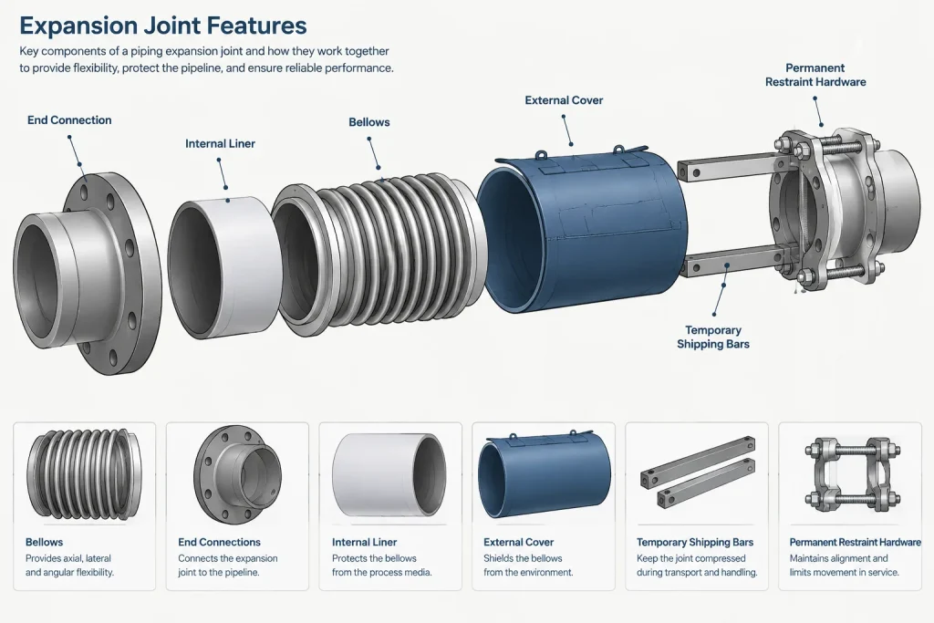
External covers protect the bellows but can hide the active element from view. Covers also affect the component envelope and may limit access to inspection points or temporary hardware. Where orientation matters, provide a positive model reference such as a direction marker, keyed insertion point, or named connection ports.
Drawing information that should be coordinated
Expansion joint documentation should direct users to verified project information without attempting to reproduce an entire vendor calculation. Depending on the project phase, drawings and schedules may need to identify:
- Component tag and line number
- Assembly type and end connections
- Installed face-to-face dimension
- Flow direction or liner direction
- Hinge, gimbal, or lateral movement orientation
- Preset or installation condition
- Temporary hardware disposition
- Associated anchors, guides, and support references
- Vendor drawing or data-sheet reference
- Insulation and external cover interfaces
Avoid placing generic movement values or load capacities in a block library unless they are linked to a verified selected item. These properties vary by design and should not be inferred from nominal size or connection type.
CAD review checklist
- Confirm that the selected assembly type matches the intended movement.
- Verify the component centerline and movement axes.
- Check face-to-face dimensions against controlled vendor information.
- Confirm whether the model represents supplied, installed, or operating geometry.
- Review pressure-thrust restraint and the documented load path.
- Coordinate anchors, guides, line stops, and nearby supports.
- Check external hardware against steel, platforms, insulation, and adjacent piping.
- Include clearance for expected movement, not only the static component.
- Verify flow direction where an internal liner or assembly design is directional.
- Distinguish temporary shipping hardware from permanent restraint hardware.
- Check that field welds or flanged joints are accessible for installation.
- Ensure component tags and references remain consistent across plans, isometrics, support drawings, and schedules.
Do not use the bellows to correct avoidable misalignment
An expansion joint should not be shown as a general-purpose allowance for construction error. Pulling, twisting, or offsetting the assembly to force mismatched pipe ends together can consume intended movement capacity and introduce loads that were not part of the design basis.
CAD coordination should place the connecting pipe ends at their specified locations and orientations. Fabrication tolerances, field-fit strategy, erection sequence, and survey requirements should be addressed separately rather than hidden inside the apparent flexibility of the bellows.
A component that connects geometry to system behavior
Metal bellows expansion joints illustrate why piping CAD cannot be limited to visible shape. Their correct application depends on movement direction, restraint, pressure forces, installation condition, and interaction with the surrounding piping and structure.
The most reliable workflow is to begin with a clearly identified placeholder, replace it with verified assembly data as selection progresses, and review the final model as part of the complete restrained piping system. This keeps the drawing useful for layout and fabrication while leaving engineering performance decisions with the responsible specialists and approved project documentation.
A controlled CAD-to-field workflow
The expansion joint model should mature with the design. Separating placeholder, selected, and issued information helps prevent preliminary geometry from being mistaken for an approved assembly.
Early routing representation
During preliminary layout, use a clearly identified placeholder with connection points, a local axis, an approximate coordination envelope based only on available project information, and a status indicating that selection is incomplete. Avoid embedding assumed movement capacity or restraint behavior.
Selected component representation
After engineering and vendor information becomes available, update the face-to-face geometry, end connections, directional features, external hardware, installation condition, and required clearance envelope. Record the controlling document reference in the component data so reviewers can distinguish verified properties from drafting conventions.
Issued installation representation
Before drawings are released for fabrication or installation, coordinate the expansion joint with the complete piping and structural arrangement. The review should include anchors, guides, supports, equipment interfaces, access, insulation, temporary hardware instructions, and the available erection sequence.
Recommended model-status controls
- Selection status: Identify whether the component is a placeholder, selected item, approved item, or field-verified assembly.
- Geometry basis: State whether the model represents supplied, installed, or another controlled condition.
- Orientation basis: Preserve flow direction, hinge axis, gimbal orientation, liner direction, and keyed connection information where applicable.
- Restraint reference: Connect the component tag to the engineering documents that define the anchor, guide, and load-path concept.
- Change control: Recheck connected piping, steel, access, and movement clearance whenever the selected assembly geometry changes.
A model can be geometrically accurate and still be functionally incomplete. The final review should therefore confirm both physical fit and the documented design intent of the restrained piping system.
Frequently asked questions
Does a CAD model need to show every bellows convolution?
Not necessarily. Simplified geometry is often sufficient when it accurately represents the connection locations, installed length, external envelope, projecting hardware, orientation, and movement-clearance needs. Detailed convolutions should be included only when they serve a defined modeling or documentation purpose.
Should the expected movement envelope be modeled?
Yes, when it supports interference and access review. The envelope should be clearly distinguished from physical material and managed according to the project CAD convention so it is not confused with the supplied component.
Can the CAD designer determine anchor and guide locations from the expansion joint shape?
No. The visible assembly does not define the required restraint system. Anchor, guide, support, and load-path decisions must come from the responsible piping flexibility and mechanical design process. CAD should document and coordinate that approved concept.
Are external rods always temporary shipping bars?
No. Similar-looking hardware may be temporary, permanent, or part of a movement-control arrangement. Its function should be confirmed from controlled documentation rather than inferred from appearance.
What should happen when vendor geometry changes after routing?
Update the controlled component and perform an impact review of connected pipe, supports, structural steel, insulation, access, field joints, orientation, and movement clearance. The revision should also be reflected consistently in drawings, schedules, and component references.
Can a bellows assembly be used to absorb construction misalignment?
It should not be treated as a general correction for mismatched pipe ends. Unplanned offset, twist, or compression can consume intended movement and introduce unintended loading. Field-fit and alignment requirements should be handled through the approved installation and engineering process.