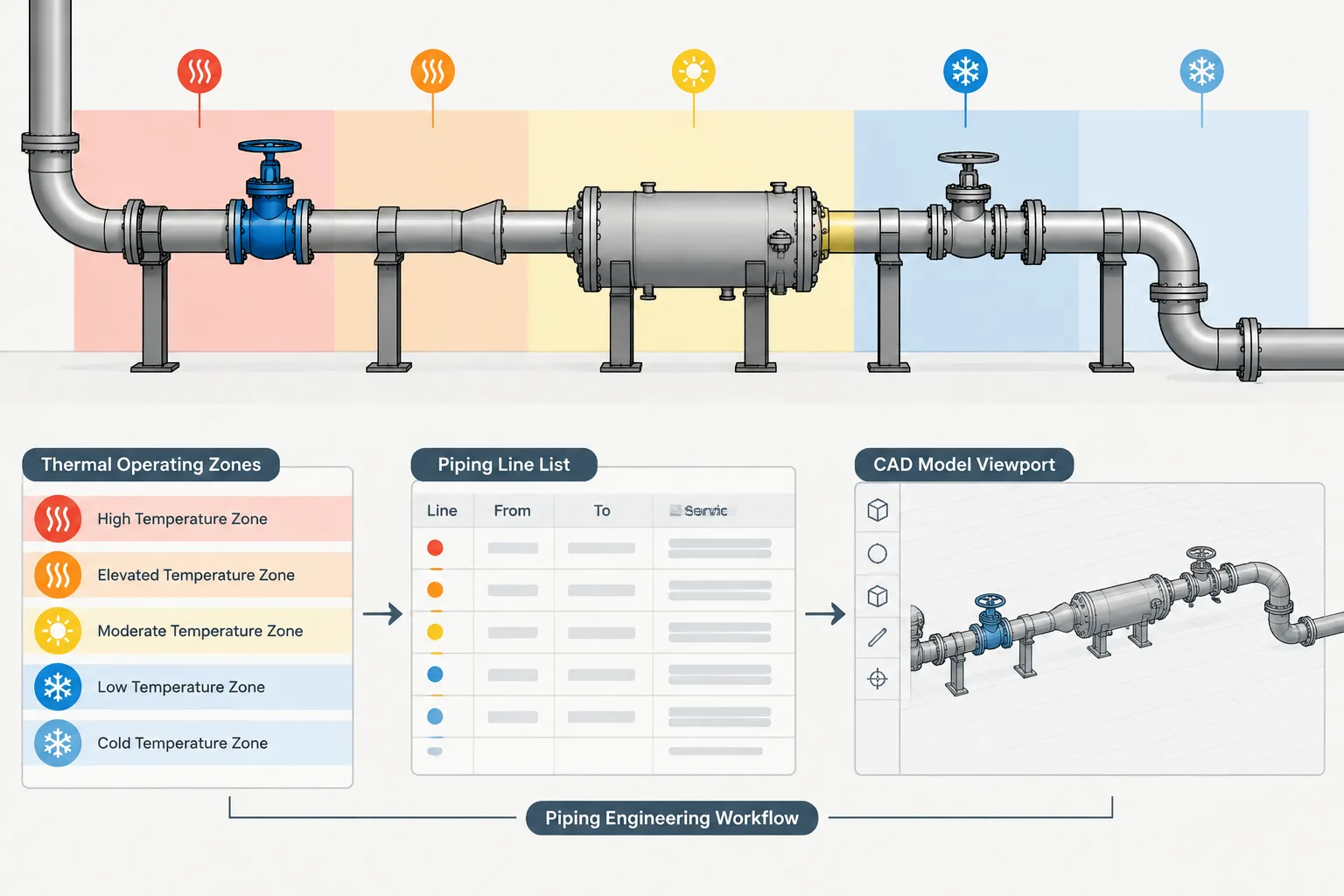
Design temperature vs. operating temperature in piping is primarily a question of engineering purpose and document control. Although both values describe thermal conditions, they are not interchangeable inputs. Each must remain connected to its condition label, units, approved source, and intended engineering use.
This guide is intended for piping designers, CAD administrators, stress analysts, and other technical users who receive temperature data from multiple project documents. It explains how to distinguish the terms, recognize incomplete information, and carry approved values into drawings and model properties without allowing CAD to replace the controlled engineering basis.
Temperature appears in piping line lists, process documents, material specifications, equipment data, stress-analysis files, and sometimes CAD properties. The same line may carry several temperature values, each serving a different purpose. Treating them as interchangeable can lead to incorrect material selection, insulation modeling, flexibility inputs, or design checks.
Piping design temperature is not simply the temperature observed during normal operation. It is a defined design input used with pressure, material data, applicable rules, and project requirements. Operating temperature describes an expected process condition. Other values may represent startup, shutdown, cleaning, regeneration, standby, upset, testing, or environmental exposure.
This guide explains the terminology and provides a practical workflow for keeping temperature data consistent without turning a CAD model into the engineering authority.
Why one piping line can have several temperatures
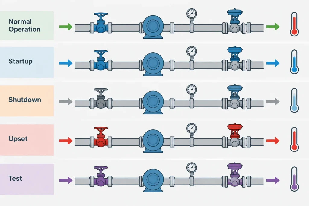
A process line rarely exists in only one condition. It may be installed at ambient temperature, heated during startup, stabilized at a normal operating condition, exposed to a short-duration upset, and later cooled for maintenance. A utility used for flushing or testing may create another condition.
Different engineering activities need different parts of this temperature profile:
- Process engineering describes expected operating cases.
- Piping engineering establishes the design basis under the applicable code and project specification.
- Materials engineering checks temperature-dependent material limitations and service requirements.
- Flexibility analysis evaluates thermal movement for relevant operating cases.
- Insulation design uses temperatures associated with heat conservation, personnel protection, condensation control, or freeze protection.
- CAD and plant-design systems represent geometry and may store approved attributes for coordination and reporting.
A single unlabeled field called “temperature” cannot reliably serve all of these purposes.
Common piping temperature terms
| Term | Practical meaning | Typical use |
|---|---|---|
| Normal operating temperature | The expected temperature during stable, routine operation. | Process description, operating review, insulation basis, and some analysis cases. |
| Maximum or minimum operating temperature | An expected operating extreme that may differ from the normal value. | Reviewing the realistic operating range and defining analysis cases. |
| Design temperature | A specified temperature used for piping design in conjunction with the design pressure and governing requirements. | Pressure design, material suitability, component selection, and piping class control. |
| Upset or abnormal temperature | A temperature associated with a credible departure from normal operation. | Process safety review and determination of whether the condition must be included in the design basis. |
| Startup or shutdown temperature | A condition occurring while the system enters or leaves service. | Thermal movement, transient review, operating procedures, and fatigue-related case definition where applicable. |
| Cleaning, steaming, or regeneration temperature | A non-production condition created by a maintenance or process cycle. | Material, gasket, lining, insulation, and flexibility checks. |
| Installation or reference temperature | The assumed temperature at which piping geometry is installed or treated as having no thermal growth. | Thermal expansion calculations and cold-position geometry. |
| Test temperature | The relevant fluid, metal, or environmental temperature during a pressure or leak test, as defined by the test procedure. | Test planning, material-condition review, temporary arrangements, and safety controls. |
Projects may use additional terms or define these terms differently. The project design basis, line-list instructions, specifications, and governing code should therefore control interpretation.
Design temperature is not a recorded operating maximum
A design temperature is an engineering value, not merely the highest number found in operating data. Its selection may require evaluation of normal operation, credible variations, control behavior, equipment interfaces, environmental effects, and the duration or frequency of particular events.
Conversely, engineers should not assume that the design temperature is a prediction of the temperature the line will continuously experience. A design value may include conditions outside routine operation, while a normal operating value should describe the expected process state.
The relationship between design pressure and design temperature also matters. Component pressure capability and material allowable values can vary with temperature. For that reason, a pressure value copied from one condition and a temperature value copied from another should not automatically be treated as a valid design pair. The responsible engineering discipline must establish the applicable combinations.
Maximum and minimum conditions both matter
High temperature is often emphasized because it can affect material strength, gasket behavior, insulation, thermal expansion, and operator protection. Low temperature can be equally important. Cooling may affect material toughness, cause condensation or freezing, contract the piping, or create a different governing flexibility case.

The lowest relevant metal temperature may not be identical to the lowest process-fluid temperature. Ambient exposure, depressurization, evaporation, intermittent flow, tracing status, insulation condition, and startup sequences may influence the actual metal condition. Determining a formal minimum design temperature is an engineering task governed by the project basis and applicable requirements.
Temperature cases in flexibility analysis
A stress model commonly needs more than one thermal condition. The analyst may compare an installed reference state with operating, startup, cleaning, standby, or upset states. Which cases are required depends on the system and the analysis basis.
The CAD model provides routing, dimensions, support locations, equipment interfaces, and component geometry, but it does not by itself define the correct thermal cases. A reliable handoff should identify:
- Reference or installation temperature assumptions.
- Relevant operating temperatures for each case.
- Whether adjacent line segments can be at different temperatures.
- Equipment nozzle movements supplied by vendors or other disciplines.
- Insulation, lining, or tracing conditions that influence the analysis model.
- Startup, shutdown, cleaning, or standby cases requiring separate review.
When a line passes through a heat exchanger, jacketed section, mixing point, or other thermal transition, one temperature assigned to the entire line number may be insufficient for analysis.
How temperature should be handled in CAD
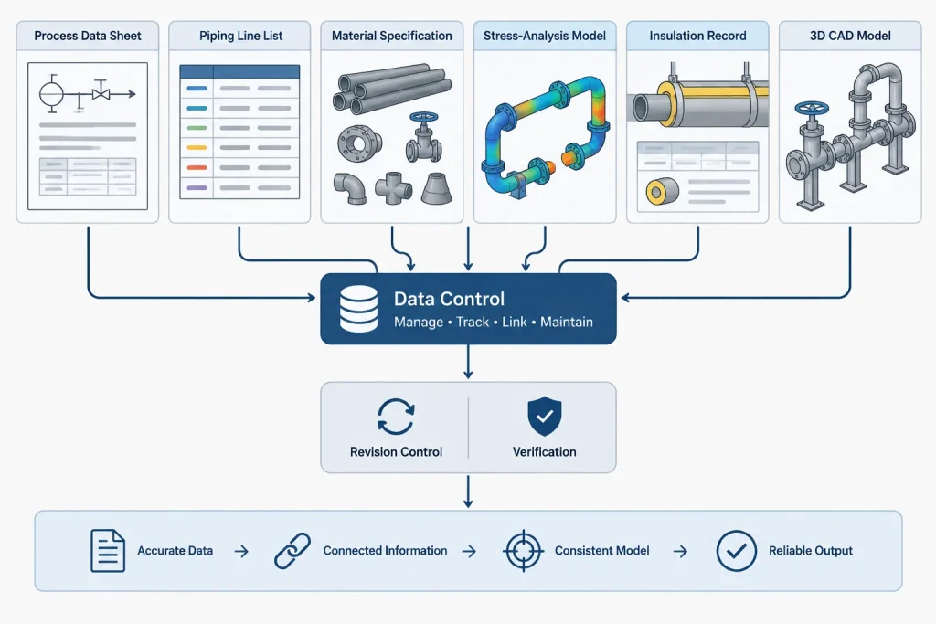
CAD and plant-design databases can store temperature attributes, but those fields should mirror controlled engineering data rather than become an independent source. The model’s primary role is geometric coordination and deliverable production.
Use clearly named properties
A property called Temperature is ambiguous. Where the software and project data structure allow it, use distinct fields such as design temperature, normal operating temperature, minimum design temperature, or analysis case identifier. Include units in the schema or reporting format rather than relying on user memory.
Do not encode engineering meaning with color alone
Model colors may help users identify hot service, insulated systems, or tracing categories, but color is not a controlled substitute for a numeric value and condition label. Colors can change through display configurations, exports, and discipline-specific view settings.
Control segment-level exceptions
If one line number includes sections with different temperature bases, define how those exceptions are recorded. Options may include separate line segments, analysis nodes, notes, or linked engineering records. Avoid silently overriding a line-level property on individual components without a documented reason.
Keep units explicit
Temperature conversion requires more than changing a unit label because temperature scales do not all share the same zero point. Absolute temperatures and temperature differences also require different treatment in some calculations. Store the unit with the value or manage it through a verified database convention.
A practical data-control workflow
- Identify the authoritative source. Establish whether approved values originate in a line list, process data sheet, engineering database, or another controlled document.
- Preserve condition labels. Transfer “normal operating,” “design,” and other terms with their values. Do not collapse them into one generic temperature field.
- Check the pressure-temperature pairing. Confirm that design values represent an approved combination rather than unrelated maxima.
- Map the data to its use. Determine which value controls piping class selection, insulation, stress analysis, equipment coordination, and reporting.
- Review transitions and exceptions. Look for exchangers, jackets, tracing limits, mixing points, depressurization cases, and intermittent services.
- Record revision status. A model property is useful only when users can determine whether it matches the current controlled source.
- Resolve conflicts through engineering review. Do not choose the most conservative-looking value or the newest-looking file without confirming the project’s document hierarchy.
Common documentation mistakes
- Using normal operating temperature as design temperature without approval.
- Keeping only the highest temperature while overlooking a critical low-temperature condition.
- Combining maximum pressure and maximum temperature even though they occur in different cases.
- Sending only one temperature to the flexibility analyst.
- Assigning one value to a full line when part of the route has a different thermal condition.
- Copying temperature values into CAD without units, condition names, source status, or revision information.
- Assuming insulation surface temperature, process-fluid temperature, and pipe-metal temperature are identical.
What a piping designer should verify
A piping designer is not normally responsible for independently establishing the design temperature, but should recognize when the available information is incomplete or contradictory. Before relying on temperature data, verify the value, unit, condition name, source document, revision, and intended use.
Temperature should be treated as a set of controlled operating and design conditions, not as a single universal property of a line. Keeping those conditions distinct improves material control, thermal analysis, insulation coordination, CAD reporting, and communication between disciplines.
Document hierarchy and temperature reconciliation
Conflicting temperature entries should be resolved through the project document hierarchy rather than by selecting the largest, smallest, or most recently edited value. A line list, process document, piping specification, analysis file, and CAD property may have different approval states or may intentionally describe different conditions.
A useful reconciliation record identifies the line or segment, condition name, value and unit, originating document, revision status, responsible discipline, and downstream uses. This makes it possible to distinguish a genuine conflict from two valid values serving different purposes.
CAD quality checks for temperature properties
- Field definition: Confirm that every property has an unambiguous name and documented purpose.
- Units: Verify that the database, reports, and drawing annotations display or inherit the intended unit convention.
- Condition: Keep design, normal operation, abnormal operation, testing, and analysis cases separate.
- Scope: Determine whether a value applies to the complete line, a segment, a component, or a specific analysis case.
- Source status: Record enough revision information to compare the model with the controlled engineering source.
- Reporting: Test whether exports preserve field names, units, condition labels, and exceptions.
Managing temperature changes
A revised temperature can affect more than a drawing annotation. The change may require review of the piping class, materials, components, gaskets, insulation, tracing, flexibility cases, support assumptions, equipment interfaces, and model reports. The responsible disciplines should determine the actual impact.
CAD teams should therefore avoid overwriting a value without preserving the approved change path. A controlled update should identify the revised source, affected model objects, dependent deliverables, and any unresolved segment-level exceptions. This approach keeps the model synchronized while leaving engineering decisions with the authorized discipline.
Practical handoff principle
Temperature data is most useful when transferred as a defined condition rather than as an isolated number. A complete handoff answers three questions: what condition does this represent, where does it apply, and which controlled source authorizes its use? If any answer is missing, the value should be clarified before it controls design or analysis work.
Frequently asked questions
Is design temperature always higher than operating temperature?
No. The relationship depends on the approved design basis and the relevant operating, abnormal, environmental, and low-temperature conditions. Designers should not infer one value from the other.
Can CAD calculate the correct piping design temperature?
CAD can store, display, validate, and report approved attributes, but it does not establish the engineering design basis. The responsible discipline must define the applicable temperature conditions.
Can one piping line have several operating temperatures?
Yes. A line may encounter different conditions during normal operation, startup, shutdown, cleaning, standby, or other project-defined cases. Different segments may also experience different thermal conditions.
Should design pressure and design temperature be stored as a pair?
They should remain associated with their approved design condition. Combining unrelated pressure and temperature extremes can create a condition that was never established by the responsible engineer.
What should a designer do when the line list and CAD model disagree?
Check the condition labels, units, document status, revision, and project hierarchy. Escalate unresolved differences through the project’s engineering review process rather than choosing a value based on appearance or apparent conservatism.
Why is a generic temperature field risky?
It does not reveal whether the value represents operation, design, installation, testing, or an analysis case. Clear property names reduce the chance that a valid value will be used for the wrong purpose.