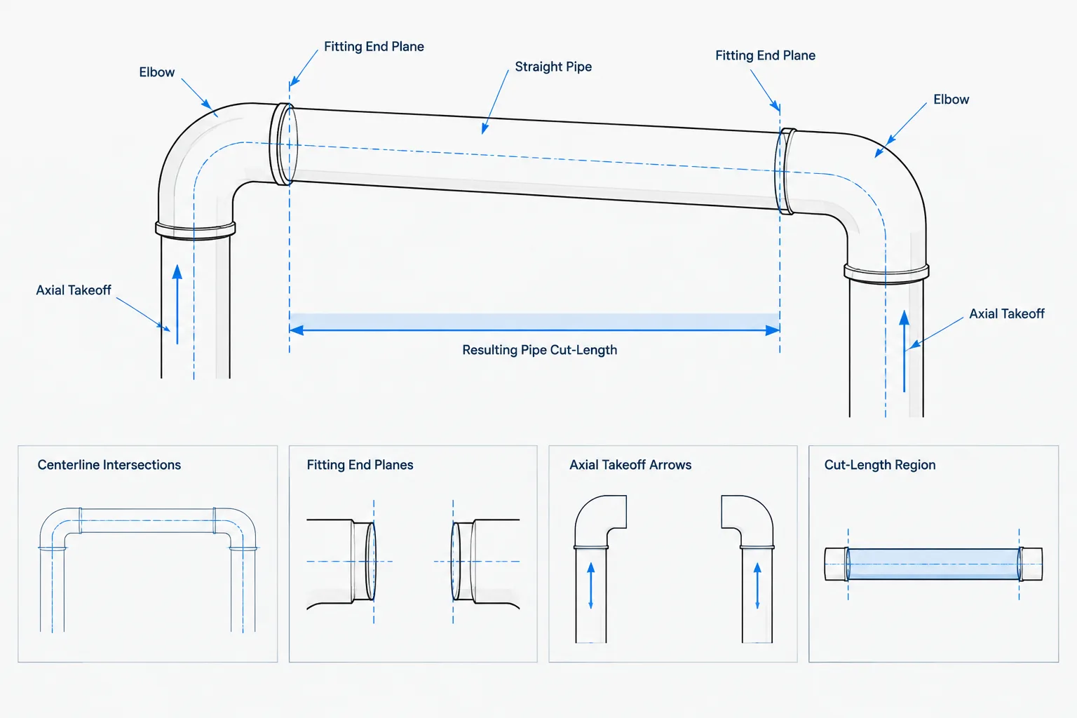
Pipe fitting takeoff in CAD connects design geometry with fabrication geometry. A routed centerline may define where piping travels, but a cut length must identify the physical connection planes that bound each straight pipe segment.
This guide explains how to interpret elbows, tees, reducers, flanges, valves, bends, and different connection types without confusing centerline intersections, component ends, or assembly references. The objective is not merely to obtain a CAD measurement, but to build a traceable dimension chain that can be checked before fabrication information is issued.
Pipe fitting takeoff is the amount of a dimensioned piping route occupied by a fitting or other component. Designers and fabricators use it to convert drawing geometry into straight-pipe cut lengths. The idea sounds simple, but mistakes occur when a drawing mixes centerline intersections, component ends, flange faces, weld locations, and actual pipe endpoints.
Takeoff is not one universal dimension that can be applied to every component. For an elbow, it may describe the distance from a theoretical centerline intersection to an end plane. For a tee, separate dimensions apply to the run and branch. A valve is normally controlled by its face-to-face or end-to-end dimension rather than an elbow-style takeoff. Connection type also determines whether insertion, engagement, weld preparation, or joint gaps must be considered.
A dependable CAD workflow therefore begins by identifying exactly what each dimension controls before any pipe length is calculated.
What Does Fitting Takeoff Mean?
In layout and fabrication work, fitting takeoff commonly means the axial or centerline distance deducted from an overall route dimension to account for a fitting. It is also called fitting allowance or fitting takeout in some shops. Terminology varies, so project documents should define which term is being used.
This meaning should not be confused with a material takeoff, which is a quantified list of pipe, fittings, valves, and other items required for a project.
A fitting takeoff is measured between defined geometric references. Depending on the component, those references may include:
- A theoretical intersection of pipe centerlines
- A fitting end plane or weld end
- A flange face
- A socket bottom or specified pipe insertion position
- The end of an internal thread
- A component center plane
- A tangent point on a bend
Without these reference points, a number labeled simply as “takeoff” can be ambiguous.
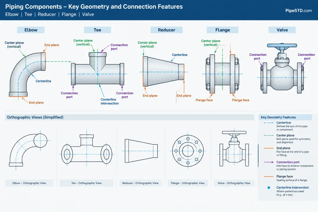
Centerline Geometry Is Not the Same as Pipe Length
CAD layouts are often developed from pipe centerlines. Centerlines make it easy to establish routing, elevations, offsets, and intersections, but they do not directly show where each piece of straight pipe begins and ends.
Consider a straight run between two elbows. The designer may dimension the distance between the theoretical intersections of the elbow centerlines. Part of that distance is occupied by each elbow, so the pipe between them is shorter than the intersection-to-intersection dimension.
In its simplest symbolic form:
Pipe cut length = controlled route distance − first component takeoff − second component takeoff
This relationship is useful only when all three dimensions are measured along the same axis and from compatible reference points. A diagonal centerline distance cannot be combined casually with a horizontal projection. Likewise, an elbow center-to-end dimension should not be deducted from a dimension that already terminates at the elbow end.
How Takeoff Differs by Component Type
| Component | Common controlling reference | Key CAD concern |
|---|---|---|
| Elbow | Theoretical centerline intersection to fitting end | Use the correct elbow geometry and angle; do not scale another size |
| Tee | Center plane to run ends and branch end | Run and branch dimensions may differ, especially for reducing configurations |
| Reducer | End plane to end plane | Its axial length occupies part of the straight route |
| Flange | Face plane, back of flange, or weld end | Identify whether the route is controlled to the flange face or pipe-side connection |
| Valve | Face-to-face or end-to-end planes | Generic geometry may not be adequate when manufacturer dimensions control |
| Socket-weld fitting | Fitting end, socket bottom, and intended pipe position | Insertion geometry and assembly requirements affect the pipe endpoint |
| Threaded fitting | Fitting end and thread makeup position | Visible end-to-end geometry does not by itself establish final assembled length |
| Pipe bend | Tangent points and bend centerline geometry | Do not treat bend tangents as elbow end planes without verification |
Elbows
For a conventional elbow, the relevant takeoff is usually associated with the theoretical intersection of the incoming and outgoing centerlines. Each end lies a defined distance from that intersection along its respective leg.
The CAD object should contain true end ports and a correctly located centerline intersection. Using the block insertion point as the dimensional reference is unsafe unless the library explicitly defines that point as the intersection. An arbitrary block origin may exist only for convenient placement.

Tees and Branch Fittings
A tee has more than one directional takeoff. The run is controlled from the component center plane toward each run end, while the branch is controlled from that center plane toward the branch end. These distances should not be assumed equal.
Branch outlet fittings require similar care. The outlet endpoint, header surface, header centerline, and theoretical branch intersection are different references. The straight branch pipe length must be based on the actual connection endpoint established by the selected component and fabrication detail.
Reducers
A reducer generally consumes an axial length between its two end planes. In a centerline model, it may appear to be only a transition in diameter, but it is still a physical component with length.
For an eccentric reducer, orientation also matters. The end planes remain important for cut length, while the offset between the connected pipe centerlines affects route geometry. Calculating only from a single continuous centerline can conceal this offset.
Flanges and Valves
Flanged assemblies should be controlled from face planes. If two equipment interfaces are dimensioned face to face, the assembly between them must account for valves, flanges, fittings, gaskets, and straight pipe according to the project’s joint representation.
A flange has several possible reference planes, including its joint face and pipe-side end. Deducting a flange thickness from a face-controlled route is not necessarily the same as deducting its pipe-side projection. The correct value depends on flange type and where the connected pipe terminates.

Connection Details Can Change the Cut-Length Logic
Butt-weld piping is often the most straightforward case because pipe and fitting weld ends establish clear nominal connection planes. Even then, the fabrication drawing must handle weld preparation and any specified assembly gap consistently. A CAD model may join nominal end planes directly while fabrication documentation communicates additional joint requirements.
Socket-weld and threaded systems require different logic. Pipe enters a socket or threaded fitting, so the pipe cut length cannot be found by measuring only between visible fitting extremities. The model or calculation must distinguish among the fitting face, internal stop or engagement reference, and intended assembled pipe position.
Grooved, mechanical, and proprietary connections may have their own end preparations and assembly positions. Their cut-length rules should come from verified component and project information rather than a generic deduction copied from another connection type.
A Reliable CAD Workflow
- Identify the controlled endpoints. Determine whether the governing dimension runs between centerline intersections, weld ends, flange faces, equipment nozzles, or another defined reference.
- Confirm component identity. Verify size, type, angle, end connection, and any configuration that affects geometry.
- Use verified dimensional data. Standardized dimensions may be suitable for generic components, while valves, specialty items, and proprietary connections may require manufacturer information.
- Locate true connection ports. CAD ports should represent physical connection planes, not merely convenient insertion points.
- Measure along the pipe axis. Use true axial distances for sloped, skewed, or offset runs rather than plan-view projections.
- Deduct only geometry not already excluded. Review the dimension chain to prevent subtracting the same fitting allowance twice.
- Apply connection-specific adjustments. Handle insertion, engagement, joint spacing, and weld preparation under the project’s fabrication rules.
- Check the assembled result. Reconstruct the chain from one controlled endpoint to the other and confirm that every component and pipe segment is represented once.
Common Takeoff Errors
- Dimensioning to the wrong elbow point: The drawing controls a tangent or end plane, but the calculation assumes a centerline intersection.
- Using nominal size as geometry: A nominal pipe designation does not provide the fitting’s center-to-end dimension.
- Scaling a fitting block: Proportional scaling does not reliably reproduce standardized geometry for another size or configuration.
- Ignoring reducing geometry: Reducing tees, reducers, and reducing outlets may shift endpoints or centerlines differently from equal-size components.
- Mixing face-to-face and end-to-end dimensions: A valve face plane, flange face, and pipe weld end are not interchangeable references.
- Using projected distance: Plan or elevation dimensions can understate the true length of a sloped or skewed pipe segment.
- Treating nominal CAD contact as fabrication detail: Components touching in a model does not prove that insertion, engagement, or weld requirements have been addressed.
What the Drawing Should Communicate
A fabrication drawing should provide an unambiguous dimensional chain without forcing the shop to infer which geometry was used. Important controlled interfaces—such as equipment faces, tie-ins, branch centers, and field-fit locations—should be clearly identified.
Not every internal fitting takeoff needs to be printed if the drawing already gives verified pipe cut lengths and component locations. Conversely, a layout drawing that shows only centerline routing should not be mistaken for a complete fabrication definition.
The central rule is simple: calculate pipe length between actual connection references, not between visually convenient points. When CAD ports, dimensions, component data, and fabrication conventions all use the same reference system, fitting takeoff becomes a dependable geometric tool rather than a source of accumulated error.
Checking the Dimension Chain Before Release
A useful quality check is to read the route as a sequence of controlled references. Begin at a known interface, follow each component and straight pipe segment in order, and stop at the next controlled interface. Every occupied length should appear once, and no allowance should be deducted twice.
The review should also separate model geometry from fabrication assumptions. A model can establish ports, axes, end planes, and component orientation. It does not automatically confirm thread engagement, socket insertion, joint preparation, field-fit allowance, or another project-specific assembly condition.
CAD Model Review Questions
- Does each component have ports at its actual connection references?
- Is the controlling route dimension axial, projected, face controlled, or centerline controlled?
- Are reducing and eccentric components oriented correctly?
- Do valve and specialty-component dimensions come from verified component information?
- Has any fitting allowance already been incorporated into a supplied cut length?
- Can the complete assembly be reconstructed from the documented dimension chain?
Practical Handoff Between Design and Fabrication
Clear handoff information identifies which dimensions are design controls and which values are fabrication outputs. Centerline routing, equipment interfaces, flange faces, branch locations, and field connections may control the layout, while individual pipe cut lengths describe the pieces required between component endpoints.
When an assembly depends on connection-specific details, those details should be established by the applicable project documentation and verified component data. A generic CAD block should not be treated as proof of an assembled length unless its ports, geometry, and reference planes have been validated for that use.
Frequently Asked Questions
Is fitting takeoff the same as pipe cut length?
No. Fitting takeoff is the portion of a controlled route occupied by a fitting or component. Pipe cut length is the remaining straight-pipe length after the applicable component geometry and connection requirements are handled.
Can a centerline measurement be used directly as a cut length?
Only when its endpoints already represent the actual pipe connection references. A measurement between theoretical fitting intersections normally includes geometry occupied by the fittings.
Where should an elbow takeoff be measured from?
It is commonly related to the theoretical intersection of the connected pipe centerlines and the relevant fitting end plane. The CAD library and verified component data must establish the exact references being used.
Why is a CAD block insertion point unreliable for takeoff?
An insertion point may have been selected only to simplify placement or rotation. Unless the block definition identifies it as a physical or theoretical dimensional reference, it should not control a cut-length calculation.
Do valves use the same takeoff method as elbows?
Generally, valves are handled through their controlling face-to-face or end-to-end geometry. Their connection planes must be matched to the route dimensions and adjacent components.
How should sloped pipe be measured?
Measure along the true pipe axis between compatible connection references. A plan or elevation projection does not represent the full axial length of a sloped or skewed segment.
What should be verified before issuing pipe cut lengths?
Confirm component identity, orientation, end connections, port locations, controlling interfaces, axial measurements, connection-specific requirements, and the complete assembled dimension chain.