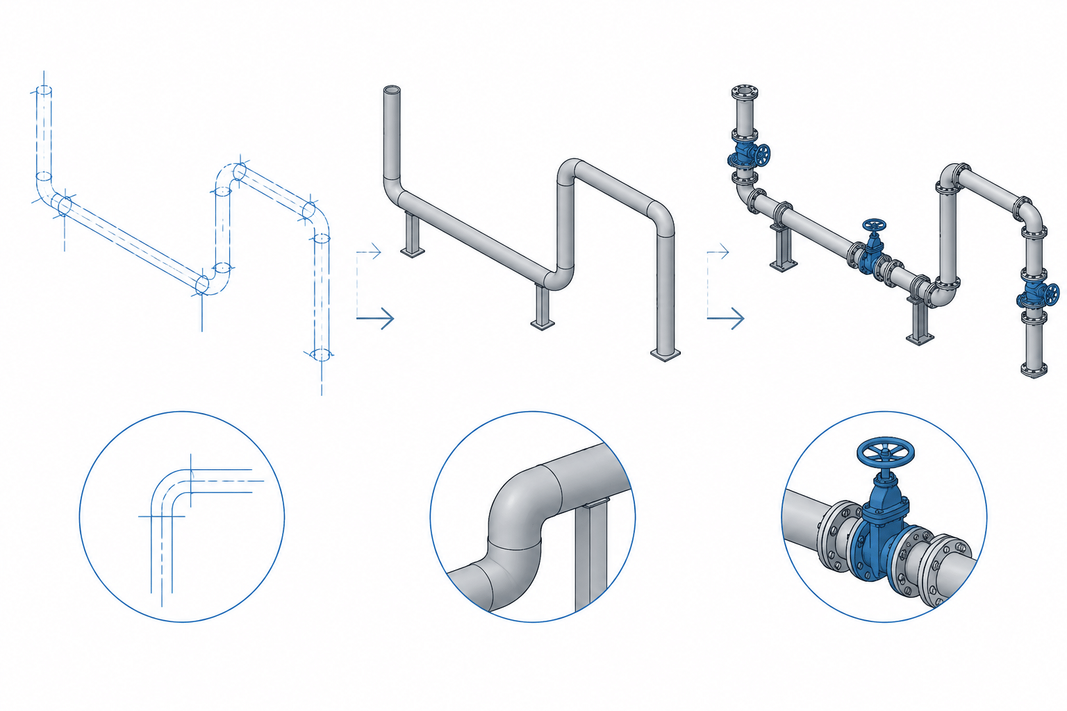
Piping CAD model level of detail should be selected according to the decision the model must support. Routing, coordination, drawing production, material reporting, and fabrication planning do not require the same geometry or data maturity.
This guide explains how to distinguish centerline accuracy from physical envelopes, identify features that control layout, manage provisional components, and document model limitations. The goal is a model that is detailed enough to be useful without creating unnecessary complexity or unsupported precision.
A piping model can be geometrically accurate without being detailed enough for every project task. Conversely, a model can contain so much small geometry that it becomes slow, difficult to maintain, and misleadingly precise. Choosing the right piping CAD model level of detail means deciding which geometry and data are necessary for the model’s intended use.
This decision affects routing studies, clash detection, drawing production, material takeoffs, fabrication planning, and handoffs between disciplines. It also determines what reviewers may reasonably infer from the model. A simplified valve body may be adequate for early routing, for example, but it may not show the operator envelope needed for an access review.
Level of detail should therefore be treated as a documented project decision rather than an informal modeling preference.
What Level of Detail Means in Piping CAD
In piping work, level of detail describes how completely a model represents the physical shape, connection geometry, metadata, and installation requirements of a system. It is not limited to visual realism.
A useful piping model may contain several kinds of detail:
- Routing detail: centerlines, nominal sizes, fitting types, and branch locations.
- Envelope detail: outside shapes needed for clearance and clash checks.
- Connection detail: end planes, flange faces, weld points, and equipment nozzle interfaces.
- Assembly detail: separate components, joint locations, spool breaks, and removable items.
- Documentation detail: tags, specifications, line numbers, service data, and bill-of-material attributes.
- Fabrication detail: verified dimensions, cut lengths, weld preparation, and shop or field assembly information.
These categories do not always develop at the same time. A model may have a well-defined route and accurate connection points while still using generic equipment or valve envelopes. Reviewers should not assume that a visually complete model is fabrication-ready.
Common Modeling Stages and Their Practical Uses
| Modeling stage | Typical content | Appropriate uses | Important limitation |
|---|---|---|---|
| Conceptual | Preliminary centerlines, approximate equipment locations, and major routing zones | Space planning, option studies, and early interdisciplinary discussion | Locations and component selections may change |
| Design routing | Nominal pipe geometry, selected fitting types, branches, valves, and primary supports | Layout development, accessibility review, and general arrangement production | Vendor-dependent dimensions may remain provisional |
| Coordination | Representative outside envelopes, insulation allowances, operators, supports, and maintenance zones | Clash detection and discipline coordination | Small fabrication features may still be omitted |
| Detailed design | Verified component dimensions, connection points, specifications, tags, and drawing data | Isometrics, material reporting, support coordination, and final design review | Construction tolerances and field conditions are not automatically represented |
| Fabrication or construction | Controlled spool geometry, weld locations, cut-length logic, joint definitions, and approved vendor interfaces | Shop detailing, assembly planning, and installation documentation | Use requires project-specific verification and document control |
These descriptions are functional rather than universal classifications. Projects and organizations may use different stage names. The important practice is to define what each stage includes, what it excludes, and which decisions may be based on it.
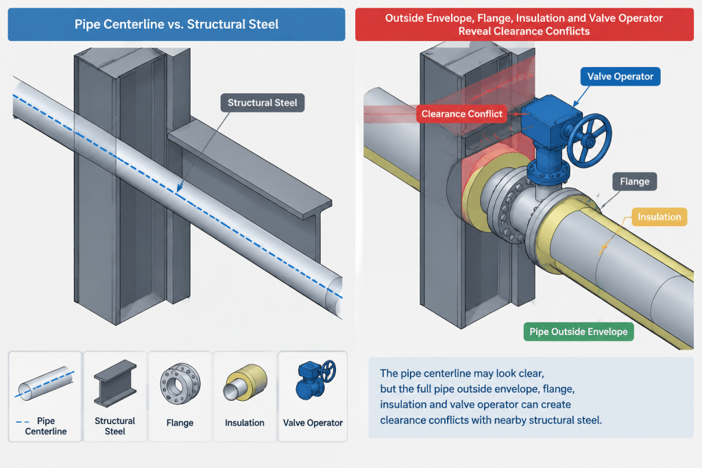
Centerline Accuracy Is Not the Same as Physical Accuracy
Centerline models are efficient for developing pipe routes. They make offsets, fitting relationships, branch locations, and elevations easy to inspect. However, a clear centerline route does not prove that the physical assembly fits.
Real piping components extend around and beyond the centerline. Flanges require space for their outside diameters and bolting. Valve bodies may be wider than adjoining pipe, while handwheels, levers, actuators, and gear operators create additional envelopes. Insulation increases the occupied diameter, and supports connect the pipe to surrounding steel or concrete.
A centerline may pass cleanly beside a structure while the flange, operator, or insulation conflicts with it. For this reason, coordination models should include the controlling outside envelopes even when minor features are simplified.
Which Features Usually Need to Be Modeled?
Pipe and fittings
Routing models generally need correct nominal sizes, centerlines, fitting categories, and end or branch locations. Detailed wall surfaces may be unnecessary unless bore geometry affects the task. A solid cylinder can represent pipe for many coordination purposes, but the model data should still identify the required pipe size and specification.
Flanges and bolted joints
A simplified flange should preserve the face location, outside envelope, and connection relationship. Individual bolts, nuts, and fine facing geometry are often unnecessary for plant-wide coordination. They may become relevant in congested joints, special bolt-access studies, or assembly details.
Valves
Valve models should represent the dimensions that control layout: connection faces, body envelope, operator orientation, and required access or removal space. Decorative cast-body features rarely improve design decisions. A generic operator can be useful early in design, but it must not be mistaken for verified vendor geometry.
Supports
Support detail depends heavily on the model purpose. Early models may show only support locations or representative symbols. Coordination models need enough geometry to identify structural interfaces and nearby clashes. Fabrication details require separately controlled information for attachments, steelwork, welds, and installation requirements.
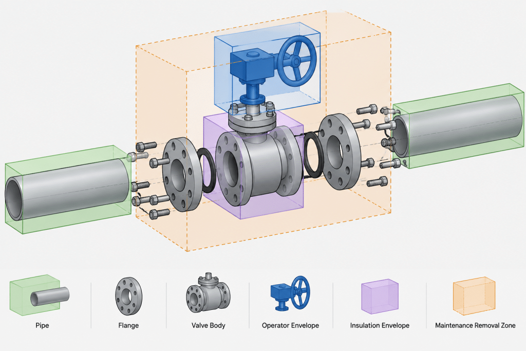
Insulation and maintenance space
Insulation is often best shown as a separate envelope, layer, or display state rather than permanently merged with the pipe geometry. Maintenance and operating clearances should also remain distinguishable from physical components. This helps reviewers understand whether a detected conflict is a hard physical clash or an intrusion into a required access zone.
Avoiding False Precision
False precision occurs when a model appears more authoritative than its source information supports. Examples include modeling a provisional equipment nozzle as though its location were final, using an arbitrary valve body shape with exact-looking dimensions, or producing fabrication measurements from generic components.
The issue is not simplification itself. Simplified geometry is often the correct engineering choice. The problem arises when its status is unclear.
Useful controls include:
- Marking provisional, generic, and vendor-confirmed components distinctly.
- Recording the source of critical component dimensions.
- Using revision status and approval fields in model data.
- Preventing placeholder components from entering final material reports unnoticed.
- Adding drawing notes where modeled geometry is representative rather than verified.
- Rechecking connected piping after vendor information changes.
Level of Detail and Model Performance
More geometry creates a computational and administrative cost. Threads, bolt threads, embossed markings, handwheel spokes, and internal valve parts may multiply object counts without improving routing or coordination. Dense component models can slow display, selection, clash processing, file exchange, and drawing extraction.
A practical component library should favor purpose-built representations. One simplified representation may support plant coordination, while a separate detailed view or external drawing supports fabrication and maintenance. Display states can also separate physical geometry, insulation, operating envelopes, and maintenance zones.
The objective is not to make every object as simple as possible. It is to include the least complex geometry that still supports the required decision reliably.
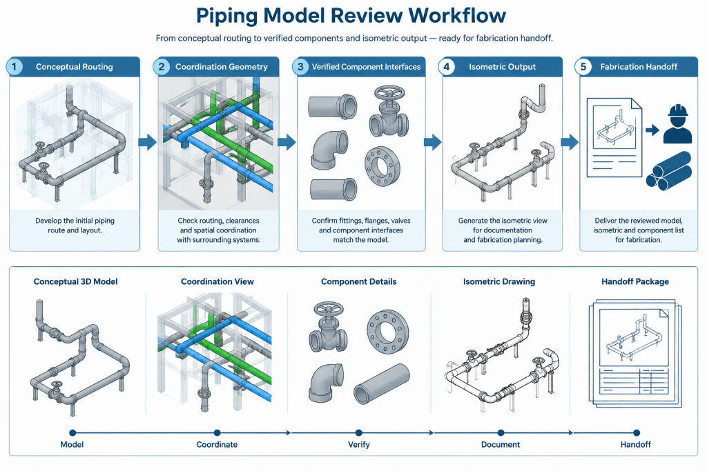
Defining Model Expectations at Project Start
A project modeling plan should state what the piping model is expected to support. The team should identify required deliverables, coordination uses, data fields, dimensional sources, and responsibility boundaries.
Questions to resolve include:
- Will the model be used only for layout, or also for isometric production and material reporting?
- Which component dimensions must be vendor-confirmed?
- Must insulation and tracing be represented?
- Are valve operators and maintenance envelopes required?
- How will provisional equipment and nozzles be identified?
- Which supports belong in the piping model, structural model, or separate support package?
- What information is excluded from the model and controlled by drawings or specifications?
Clear answers prevent different disciplines from relying on the same model in incompatible ways.
A Practical Review Workflow
Before issuing or reusing a piping model, review it against its stated purpose:
- Confirm intended use. Determine whether the review concerns routing, coordination, documentation, fabrication, or another task.
- Check controlling geometry. Verify centerlines, connection faces, component envelopes, operators, insulation, and access zones as applicable.
- Identify placeholders. Find generic valves, provisional nozzles, estimated equipment, and unresolved supports.
- Validate model data. Check line numbers, sizes, specifications, component tags, and status fields against controlled project documents.
- Review omissions. Confirm that excluded details are documented and available from another controlled source.
- Record limitations. State what users must not derive from the model without further verification.
The Model Must Be Fit for Its Decision
An effective piping CAD model is not necessarily the most visually realistic model. It is the model that communicates the right geometry and data for the decision being made. Concept routing needs flexibility, coordination needs reliable envelopes, detailed design needs controlled interfaces, and fabrication needs verified component and assembly information.
By defining level of detail in terms of model purpose, piping teams can reduce false precision, improve performance, clarify handoffs, and prevent users from drawing conclusions that the available information does not support.
Detail, Accuracy, and Status Are Different
Model detail describes what has been represented. Accuracy describes how closely that representation matches controlled dimensional information. Status indicates whether the information is preliminary, reviewed, vendor-confirmed, approved, or otherwise governed by the project workflow. These qualities should not be treated as interchangeable.
A visually elaborate component can still be based on provisional information. A simple envelope can be accurate enough for coordination when its connection locations and controlling outside shape come from an accepted source. Review procedures should therefore examine geometry, source, and status separately.
Match Each Model Element to a Required Decision
- For routing: prioritize centerlines, component relationships, branch locations, and connection continuity.
- For coordination: add the outside envelopes that can create physical, insulation, access, support, or operating conflicts.
- For documentation: verify that tags, line information, specifications, and component attributes remain consistent with controlled project records.
- For fabrication planning: require verified interfaces, joint definitions, assembly boundaries, and dimensions from approved sources.
- For handoff: identify placeholders, exclusions, unresolved interfaces, and information maintained outside the model.
Use Model Views to Communicate Intent
A single representation does not have to serve every review. Purpose-specific display states can separate routing geometry, physical equipment, insulation, support interfaces, operating envelopes, and maintenance space. This approach makes clashes easier to interpret and reduces the risk that clearance zones will be mistaken for installed material.
When detailed component geometry is maintained separately, the coordination model should retain stable reference points and clear identifiers. Users can then trace a simplified object to its controlled component information without burdening the main model with features that do not support the current task.
Model Acceptance Should Follow Defined Criteria
A useful review asks whether the model satisfies its declared use, not whether every object looks realistic. Acceptance criteria should identify which interfaces and envelopes must be checked, which data fields must be complete, how provisional content is marked, and which information remains controlled by drawings, specifications, vendor documents, or field verification.
Any reuse outside the original purpose requires a fresh review. Geometry prepared for spatial coordination should not automatically be treated as fabrication geometry, and a model issued for drawing production should not be assumed to represent construction tolerances or actual field conditions.
Frequently Asked Questions
What is piping CAD model level of detail?
It is the defined amount of physical geometry, connection information, metadata, and installation-related representation included to support a particular piping task. It concerns model function, not merely visual realism.
Does a detailed-looking model guarantee dimensional accuracy?
No. Fine geometry can still come from generic or provisional information. Dimensional authority depends on the source, verification status, and project controls associated with the component.
Is centerline geometry enough for clash detection?
Centerlines help evaluate routing but do not represent the full occupied space. Coordination generally requires the controlling envelopes of components, operators, insulation, supports, and applicable access zones.
Should every bolt, thread, and internal valve feature be modeled?
Only when that feature supports a defined review, assembly, access, or documentation need. Otherwise, such geometry may increase model complexity without improving the decision.
How should generic valves and provisional equipment be handled?
They should be clearly identified by status and kept distinguishable from verified components. Their connection assumptions, controlling envelopes, and known limitations should be recorded so users do not treat them as final vendor geometry.
Can one model representation support every project phase?
Not necessarily. Different display states, component representations, or controlled supporting documents may be more effective for routing, coordination, documentation, fabrication planning, and maintenance review.
When should the model level of detail be reviewed?
Review it when the intended use changes, new vendor information arrives, interfaces are revised, deliverables advance, or the model is transferred to another discipline or organization.