
Design pressure and design temperature are controlled inputs that connect process engineering with piping design and CAD documentation. They help determine which line data, piping specification, components, and interfaces must be reviewed together.
This reference explains how to preserve that connection without confusing design conditions with normal operating readings. It also shows how to identify specification changes, check document consistency, and raise unresolved conflicts instead of resolving them by assumption.
Design pressure and design temperature are among the most important process inputs carried into piping documentation. They influence material specifications, component selection, inspection requirements, insulation decisions, and the way a line is identified in engineering documents. Yet these values are often misunderstood during CAD work because they may differ from the pressure and temperature normally observed during operation.
A piping drawing does not usually perform the complete pressure design. Its job is to communicate the approved design basis clearly enough that the correct pipe, fittings, flanges, valves, gaskets, and other components can be selected and verified. A reliable CAD workflow therefore treats pressure and temperature as controlled line data, not as values to be guessed from a component appearance or copied casually from a nearby line.
Design conditions versus operating conditions
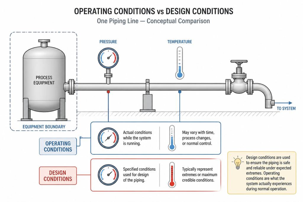
Operating pressure and operating temperature describe expected conditions during a defined mode of operation. A line may have different operating conditions during startup, normal production, shutdown, cleaning, regeneration, or another process state.
Design pressure and design temperature are engineering inputs used to establish the conditions for which the piping system and its components must be evaluated. They are not necessarily the maximum values shown by an operator’s normal reading, and they should not be inferred from the line’s current service alone.
This distinction matters in CAD because a drawing may show a single line number and a single piping specification while the process documents contain several operating cases. The approved design basis should determine which conditions govern the piping class or line requirements. If the basis is unclear, the drafter should identify the discrepancy rather than selecting a value based on visual judgment.
Where the information comes from
Pressure and temperature data may be distributed across several project documents. Common sources include the process line list, P&ID, equipment data, piping material specification, process design criteria, relief-system information, and project notes. The exact document hierarchy varies by project, so the current approved source should be confirmed before drafting or revising a line.
A practical review begins by checking whether the following information is available:
- Line number and service description
- Normal and applicable operating conditions
- Design pressure and design temperature
- Fluid phase or service category, where required by the project
- Material specification or piping class
- Connection points and equipment limits
- Special conditions such as vacuum, cycling, steam-out, cleaning, or low-temperature operation
- Any transition between different piping specifications
These inputs should be compared rather than read in isolation. For example, an equipment nozzle may have a pressure or temperature limit that affects the connected line, while a branch may change to another material specification because its service or design basis differs from the main header.
How pressure and temperature appear in piping documentation
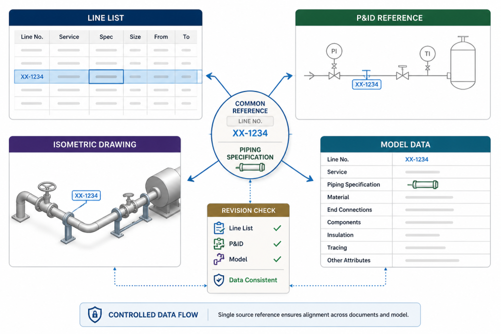
Not every drawing displays the actual design values. In many projects, the line number points to a line list or database, while a piping specification identifies the permitted component families. Other projects place design conditions in a title block, line data table, general note, or dedicated schedule.
The CAD deliverable should make the relationship between the line and its controlling data unambiguous. A reviewer should be able to determine:
- Which line record applies to the drawn segment
- Which piping specification governs the components
- Where the design conditions are recorded
- Whether the line changes specification or design basis at a defined point
- Whether connected equipment or specialty items impose additional limits
| Information | Typical CAD or project location | Drafting check |
|---|---|---|
| Line number | P&ID, line list, isometric, or model database | Confirm that the identifier is consistent across views and documents. |
| Design pressure | Line list, design basis, or controlled project database | Do not substitute normal operating pressure without approval. |
| Design temperature | Line list, process document, or material specification basis | Check startup, shutdown, cleaning, and other governing conditions. |
| Piping specification | Line list, P&ID, specification assignment, or model properties | Verify that fittings, flanges, valves, and gaskets match the assigned class. |
| Specification break | P&ID, isometric, plan, or model annotation | Show the break at a defined location and preserve both line identities. |
Using design conditions during CAD setup
1. Establish the line record before modeling
Before placing components, confirm the line number, service, size, material specification, and design conditions in the project database or approved line list. This prevents a common error: drawing a visually plausible route and assigning the line data afterward.
When a line has multiple operating modes, do not compress the information into an ambiguous note. Record the governing design inputs according to the project workflow and flag any unresolved condition for process or piping engineering review.
2. Assign the correct piping specification
The design pressure and temperature do not, by themselves, identify every component needed for a line. The piping specification converts the approved design basis into a controlled set of materials, component types, end connections, pressure classes, gasket requirements, and other project rules.
During CAD work, use the specification assignment as a consistency check. A valve, flange, reducer, branch fitting, or specialty item should not be selected merely because it fits geometrically. Its material, connection type, pressure class, and temperature suitability must agree with the governing project data.
3. Check changes along the route
Design conditions may change at equipment boundaries, battery limits, utility tie-ins, process transitions, or specification breaks. A line that appears continuous in plan view may contain a data transition that must be shown in the isometric, model properties, or line list.
At each change, check whether the drawing needs a new line number, a specification-break symbol, a note, a flange, or another defined interface. Do not hide the transition inside a crowded area where a reviewer cannot determine which specification applies to each component.
Common CAD mistakes and why they matter
Copying conditions from a nearby line
Adjacent lines may carry different fluids, temperatures, pressures, or materials. Proximity is not evidence that the design basis is the same. Copying line data can produce a correct-looking drawing with incorrect component assignments.
Treating pressure class as design pressure
A component pressure class or rating designation is not a replacement for the line’s design pressure and temperature record. Component applicability depends on the relevant conditions, materials, geometry, and project requirements. Use the approved specification and engineering review process rather than treating one label as a complete design check.
Showing operating values without identifying them
A value copied from a process display, P&ID annotation, or operator document may represent normal operation rather than the design basis. If operating and design values are both shown, label them clearly so the reader cannot mistake one for the other.
Ignoring non-normal conditions
Startup, shutdown, cleaning, steam-out, blocked-in heating, vacuum, and upset scenarios can affect the design basis. The CAD drafter is not expected to calculate these cases, but should recognize when a line record or engineering note refers to them and avoid overwriting the approved data with normal-condition values.
A practical review workflow
- Identify the line number and confirm the current revision of its source data.
- Record the design pressure and design temperature separately from normal operating values.
- Confirm the assigned piping specification and any applicable material or service restrictions.
- Review equipment connections, branches, valves, flanges, and specialty components for matching line data.
- Locate specification breaks and verify that each side of the break is identified.
- Compare the isometric, plan, P&ID, line list, and model properties for consistent identifiers.
- Mark unresolved conflicts as engineering queries or review comments; do not silently resolve them by assumption.
Why clear data improves the drawing
Correct pressure and temperature information supports more than component selection. It improves model queries, bill-of-material extraction, spool review, procurement data, inspection planning, and change control. It also helps reviewers distinguish a drafting problem from a process-data problem.
The most useful piping drawings do not merely display geometry. They preserve the relationship between geometry and the approved design basis. By separating operating conditions from design conditions, linking each line to its controlled specification, and showing transitions clearly, a CAD team can reduce assumptions and make downstream review more reliable.
How to use this reference during a CAD review
Use the existing technical guidance as a coordination checklist rather than as a substitute for the approved project design basis. The most reliable workflow follows the data from its controlled source into the line record, piping specification, model properties, drawings, and review comments.
- Start with identity: Confirm that the line number, service, route, and connected equipment are being considered as one coordinated record.
- Separate condition types: Keep normal operating information distinct from design inputs and clearly label both when they appear in project documentation.
- Follow the interface: Review branches, equipment nozzles, specialty items, and specification breaks instead of checking only the main run.
- Preserve traceability: Make sure a reviewer can determine which approved source controls the displayed line information.
- Escalate uncertainty: A drafting deliverable should expose conflicting or missing data through a review comment or engineering query, not conceal it through an unverified selection.
This topic connects closely with piping material specifications, line lists, P&IDs, isometric drawings, model databases, equipment limits, and bill-of-material workflows. Treating those relationships as part of the CAD task helps prevent drawings that look complete but carry incorrect engineering data.
Frequently Asked Questions
Are design pressure and operating pressure the same?
No. Operating pressure describes an expected process condition, while design pressure is an engineering input used to evaluate the piping system and its components. The approved project basis should control which value is used for design documentation.
Where should design pressure and temperature be shown?
The location depends on the project workflow. They may be held in a line list, controlled database, design-basis document, piping specification, drawing note, or schedule. The important requirement is that the applicable source and line record are unambiguous.
Can a drafter select components from a nearby line?
No. Adjacent lines can have different services, materials, design conditions, or piping specifications. Component selection should follow the approved data for the specific line and interface being drafted.
Does a component pressure class replace the design pressure record?
No. A pressure class or rating designation is only one part of component applicability. Material, temperature, geometry, connection details, and project requirements must also be considered through the approved engineering workflow.
What should happen when documents show conflicting conditions?
Compare the current approved sources and identify the discrepancy through the project review or engineering-query process. Do not silently select a value based on appearance, proximity, or a normal operating reading.
Why are non-normal conditions important in CAD coordination?
Startup, shutdown, cleaning, steam-out, vacuum, blocked-in heating, and upset conditions may affect the governing design basis. The drafter does not normally calculate these cases, but should preserve relevant approved information and flag uncertainty for engineering review.