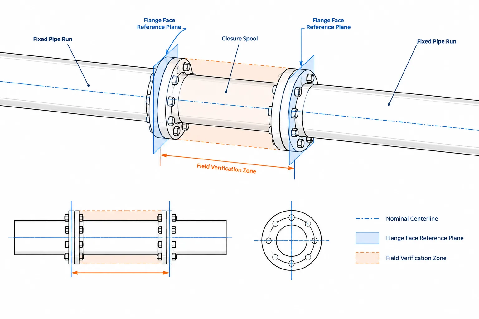
Field-fit piping in CAD requires more than an oversized pipe segment or a general construction note. The model, fabrication drawing, field survey, and release process must identify exactly which geometry is confirmed and which portion remains subject to site measurement.
This guide explains how trim allowances, closure spools, held dimensions, and verified interfaces work together. It also helps piping designers and drafters choose an adjustment strategy that matches the actual direction and type of uncertainty.
Field-fit piping is used when a final fabricated dimension cannot be established reliably from design data alone. Existing pipe may not match old drawings, equipment may shift during installation, or a connection may need to close between two fixed interfaces. In these situations, the CAD model can show design intent, but it cannot replace a controlled field measurement.
The solution is not simply to make a pipe longer and tell the installer to cut it. A usable field-fit arrangement identifies what remains uncertain, where adjustment is permitted, which dimensions must be verified, and when the affected spool may be released for final fabrication.
What field fit means in piping work
A field-fit item contains a deliberately controlled portion whose final geometry is established from actual installation conditions. Depending on project terminology, this may be called a field-fit spool, closure spool, trim piece, make-up piece, or field-adjusted section.
These terms are not automatically interchangeable. A project should define them in its fabrication and construction procedures. In general:
- Field-fit spool: A spool with one or more dimensions finalized or trimmed at the installation site.
- Closure spool: A spool used to complete the gap between installed systems or fixed interfaces after their actual positions are known.
- Trim allowance: Deliberate additional material provided at a designated end for controlled cutting and end preparation.
- Hold dimension: A dimension that is not released as final until specified information or a field measurement becomes available.
- Field verification: The process of measuring and confirming actual coordinates, orientations, elevations, or joint conditions before fabrication or final trimming.
Field fit should be treated as an exception managed by the project workflow, not as a substitute for resolving avoidable design uncertainty.
Why CAD geometry may not be enough
A piping model usually represents nominal design geometry. Existing facilities and installed equipment contain conditions that may not appear in that model. Typical sources of uncertainty include:

- Existing piping that was modified without a reliable as-built update
- Equipment nozzle positions that depend on final setting, leveling, or vendor installation
- Structural steel, supports, or penetrations installed within permitted tolerances
- Multiple fabricated runs approaching the same closure point
- Buried or concealed piping whose exact route cannot be confirmed visually
- Flange faces that are offset, rotated, or not square to the expected centerline
- Site weld preparation and fit-up conditions that differ from nominal model geometry
Increasing the apparent precision of a CAD dimension does not remove these uncertainties. If the endpoint was never surveyed, adding more decimal places only gives uncertain information a false appearance of accuracy.
Field-fit strategies and their uses
| Strategy | Typical purpose | Primary control concern |
|---|---|---|
| Trimmed straight end | Absorb uncertainty mainly along one pipe axis | Available straight length and correct end preparation after cutting |
| Closure spool | Connect two installed interfaces after measurement | Complete geometry between both endpoints, including orientation |
| Loose-shipped component | Permit final assembly or orientation at the site | Identification, installation direction, and responsibility for fit-up |
| Held fabrication dimension | Delay final fabrication until survey data is approved | Release status and prevention of premature manufacture |
| Field-routed small connection | Accommodate local conditions where permitted by project practice | Minimum layout requirements, support, drainage, access, and material class |
The appropriate strategy depends on the type of uncertainty. A straight trim allowance can compensate for axial variation, but it cannot automatically correct lateral offset, angular error, flange rotation, or an incorrect elevation. When uncertainty exists in several directions, a separately measured closure spool may be more controllable.
Choosing a useful location for field adjustment
A field-fit location should be accessible for measuring, cutting, alignment, welding, inspection, and any required examination. It should also minimize the number of variables that must be resolved at once.
A practical location generally has sufficient straight pipe, a clear measurement reference, and a reasonable path for installing the final piece. Locations crowded by elbows, branch connections, supports, insulation transitions, or equipment may leave too little room for trimming and end preparation.
The designer should also review:

- Whether the spool can be transported and inserted after surrounding work is installed
- Whether the designated joint can be reached by fabrication and inspection personnel
- Whether trimming would interfere with a fitting tangent, branch reinforcement, lining, coating, or special end treatment
- Whether nearby supports depend on the spool’s final length or center of gravity
- Whether flange alignment must be established before the closure piece is measured
- Whether construction sequence could block access to the fit-up location
Field adjustment should not be placed casually at the most convenient drafting break. Its physical work area and installation sequence must be checked.
How to represent field-fit piping in CAD
Model the intended system geometry
The model should normally show the intended route, components, connection types, and nominal interfaces. It should not disguise uncertainty by modeling an arbitrary offset or by stretching a fitting. Standard components should retain their correct nominal geometry.
Identify the controlled adjustment zone
Mark the spool, pipe end, or joint where adjustment is permitted. The note should state the required action clearly, such as field verify before fabrication, provide trim material at the indicated end, or fabricate closure spool after installed interfaces are surveyed.
A generic note such as “field fit” is often insufficient. It does not tell fabrication which end may be trimmed, which dimension is held, or whether the spool is expected to arrive oversized.
Distinguish final dimensions from reference dimensions
Dimensions based on confirmed design geometry should remain separate from dimensions that depend on site measurement. A held or reference dimension must be presented according to the project’s drafting convention so that it cannot be mistaken for a released fabrication requirement.
Do not create a conflicting dimension chain in which the overall location, individual spool lengths, and a field-adjusted segment are all shown as independently controlling values.
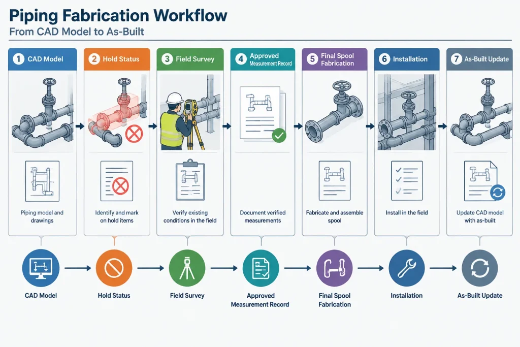
Coordinate model and drawing status
If the model contains nominal geometry while the drawing requires field verification, the data status should be visible to downstream users. A fabricator, material takeoff user, or construction planner should not assume that every modeled pipe length is approved for cutting.
What must be measured in the field
A single face-to-face distance may not fully define a closure. The required survey information depends on the connection geometry but can include:
- Endpoint coordinates or offsets from established project datums
- Pipe centerline elevation and direction
- Flange-face location and plane
- Bolt-hole orientation where relevant to assembly
- Existing pipe outside diameter and end condition
- Available straight length for cutting and welding
- Obstructions affecting spool insertion or welding access
- Actual support, wall, floor, or penetration locations
Measurements should be tied to identifiable reference points. A sketch that says only “distance between pipes” may be unusable if the measured points, face planes, or centerlines are not defined.
A controlled field-fit workflow
- Define the uncertainty. Record whether it concerns axial distance, elevation, lateral position, rotation, or several variables.
- Select the adjustment method. Decide whether trimming, delayed fabrication, a closure spool, or another approved construction method is appropriate.
- Mark the affected model and drawings. Identify the held dimension, adjustable end, field joint, and any required installation sequence.
- Issue a measurement request. Specify the required datums, endpoints, orientation information, and expected survey record.
- Verify surrounding installation status. Confirm that the measured interfaces are fixed and will not move during later alignment or setting work.
- Update or supplement the fabrication information. Incorporate accepted field data without erasing the traceability of the original hold condition.
- Release the item through document control. Ensure fabrication is working from the authorized revision or approved field sketch.
- Capture the installed condition. Update the as-built record when the completed arrangement differs from nominal design geometry.
Common documentation failures
- Unbounded extra length: The drawing requests additional pipe but does not identify the trim end or final reference plane.
- Wrong adjustment direction: Axial trim is used even though the main uncertainty is lateral or angular.
- Premature survey: A closure is measured before equipment, piping, or steel is in its final secured position.
- Hidden model status: A nominal model length enters a cut list even though the corresponding dimension is still held.
- Missing end-work instructions: The drawing permits cutting but omits responsibility for restoring the specified bevel, thread, groove, coating, lining, or other end condition.
- No installation path: The final spool geometry is valid, but the completed piece cannot be moved into position.
- Weak traceability: Field measurements are communicated informally without a controlled sketch, revision, or approval record.
Final drafting principle
Good field-fit documentation separates known geometry from unresolved geometry. It tells the shop what may be fabricated, tells the field what must be measured, and tells document control what must happen before final release. CAD provides the design framework, but actual site conditions must establish the dimensions that the model cannot reliably predict.
When uncertainty is explicit and limited to a planned adjustment zone, field fit becomes a controlled construction method rather than an improvised correction.
Turning field uncertainty into controlled information
A field-fit designation should function as a data-control instruction, not merely as a visual annotation. Anyone using the model or drawing should be able to determine the affected item, the unresolved condition, the permitted adjustment, and the approval needed before fabrication proceeds.
Separate geometry uncertainty from fabrication allowance
These concepts are related but different. Geometry uncertainty describes what is not yet known about the installed interfaces. A fabrication allowance is the material or adjustment method provided to resolve a defined portion of that uncertainty. Adding material does not solve an offset, orientation, or access problem unless the selected adjustment can accommodate it.
Make the handoff visible
The field-fit workflow crosses several responsibilities. Design defines the intended route and acceptable adjustment zone. Field personnel document the installed interfaces from recognized references. Fabrication uses only released information, while document control preserves the status and revision history. Construction then confirms the completed condition for the as-built record.
Useful CAD properties, drawing notes, spool identifiers, and status fields should support the same message. Conflicting instructions between the model and fabrication document can cause nominal geometry to be treated as a final cut requirement.
Review the closure as an assembly
A closure should be checked as part of the surrounding installation rather than as an isolated length of pipe. The review should consider whether the interfaces are fixed, whether the piece can be inserted, whether joints remain accessible, and whether the final arrangement is compatible with nearby supports and components.
Field-fit drawing review questions
- Is the source of uncertainty stated clearly?
- Is the adjustable spool, end, or joint unmistakably identified?
- Does the selected method address the direction of uncertainty?
- Are held and reference dimensions distinguishable from released fabrication dimensions?
- Are the field measurement points and reference datums defined?
- Is responsibility for cutting, end preparation, examination, and release clear?
- Can the completed spool be transported into position and installed?
- Will downstream cut lists, material reports, and fabrication exports preserve the hold status?
- Is there a controlled path for recording the final installed geometry?
If these questions cannot be answered from the issued information, the field-fit instruction may transfer ambiguity rather than control it. The drawing should be clarified before the affected work is released.
Frequently asked questions about field-fit piping
Is a field-fit spool the same as a closure spool?
Not necessarily. A field-fit spool generally contains geometry that will be finalized or adjusted from site information. A closure spool specifically completes the space between installed interfaces after their actual relationship is established. Project procedures should define the terms used on drawings and fabrication documents.
Can a trim allowance correct any piping mismatch?
No. Trimming primarily addresses variation in the permitted cutting direction. It does not inherently correct lateral displacement, angular misalignment, elevation error, or flange rotation. The adjustment method must match the uncertainty.
Should CAD show the pipe at its nominal or oversized length?
The model should communicate intended geometry without concealing unresolved conditions. Whether additional trim material is modeled or controlled through fabrication information depends on project practice. In either case, the adjustable end, hold status, and fabrication instruction must be clear to downstream users.
When should a closure spool be measured?
Measurement should occur after the relevant interfaces are installed, secured, and unlikely to move through later setting or alignment work. The survey request should identify the reference points, interface conditions, and orientation information needed to define the spool.
Why is a face-to-face measurement sometimes insufficient?
A single distance may omit centerline direction, elevation, flange plane, rotation, offsets, or installation constraints. The required field record should describe enough geometry to reproduce the relationship between both interfaces.
What should happen after field dimensions are accepted?
The approved information should enter the controlled fabrication workflow. Drawings, sketches, model status, and release records should remain coordinated so that the shop uses the authorized geometry and the completed condition can be captured for as-built documentation.