Tag: fabrication drawings

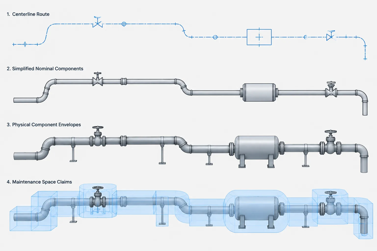
  • Piping CAD Level of Detail: Centerlines, Space Claims, and Fabrication Geometry

    Piping CAD Level of Detail: Centerlines, Space Claims, and Fabrication Geometry

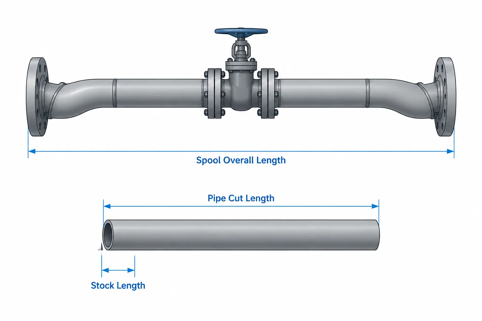
  • Pipe Length Terminology: Stock Length, Cut Length, Developed Length, and Spool Overall Length

    Pipe Length Terminology: Stock Length, Cut Length, Developed Length, and Spool Overall Length

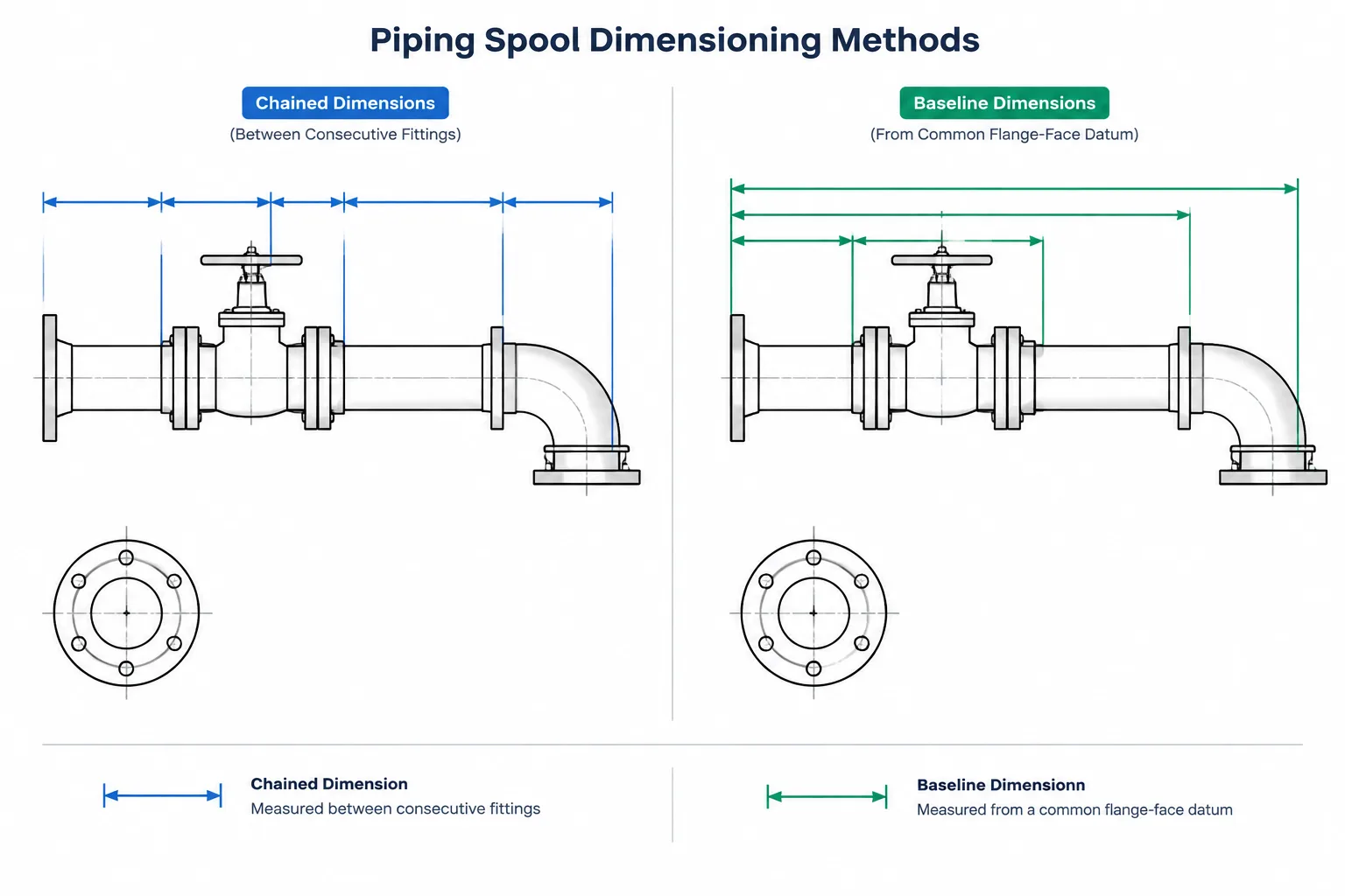
  • Piping Dimension Chains vs. Baseline Dimensions in CAD: Controlling Fit-Up and Accumulated Variation

    Piping Dimension Chains vs. Baseline Dimensions in CAD: Controlling Fit-Up and Accumulated Variation

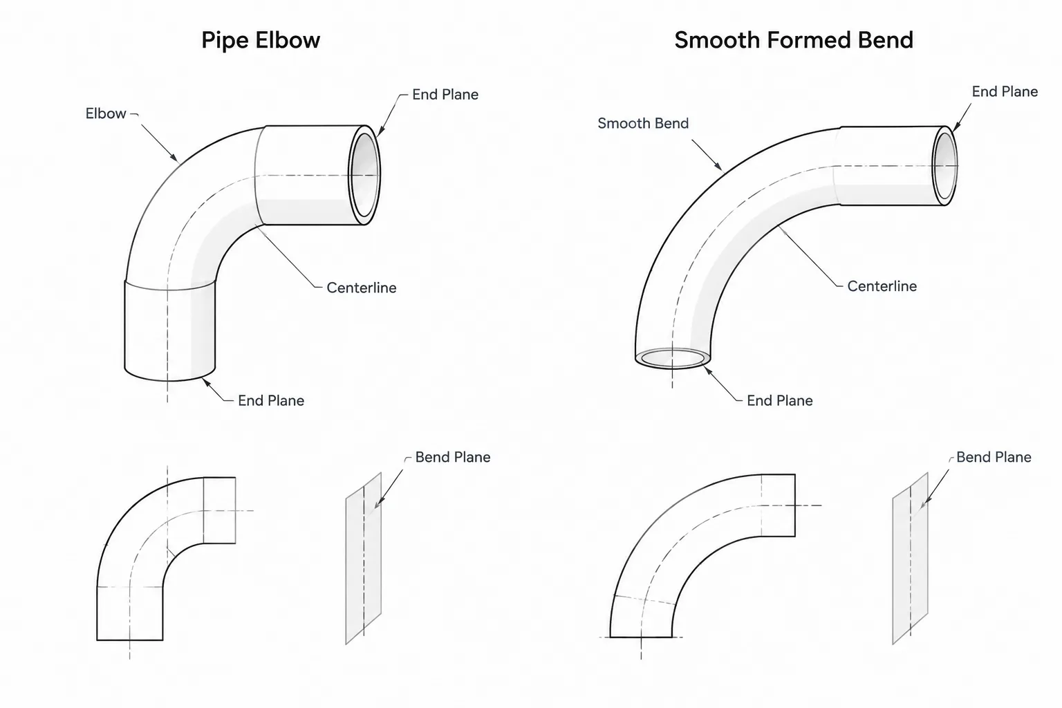
  • Pipe Bends vs. Elbows in CAD: Geometry, Fabrication, and Documentation

    Pipe Bends vs. Elbows in CAD: Geometry, Fabrication, and Documentation

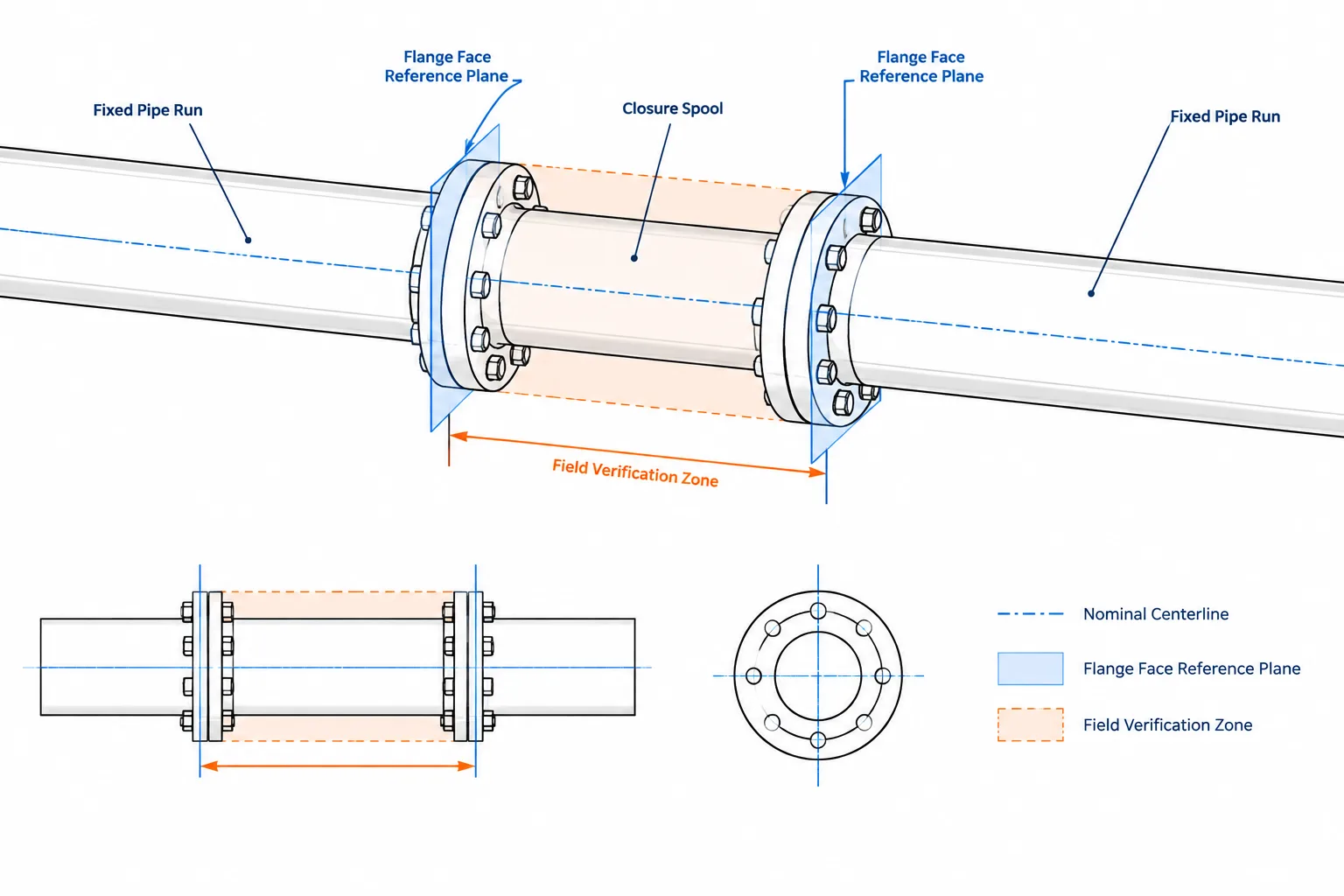
  • Field-Fit Piping in CAD: Trim Allowances, Closure Spools, and Verified Dimensions

    Field-Fit Piping in CAD: Trim Allowances, Closure Spools, and Verified Dimensions

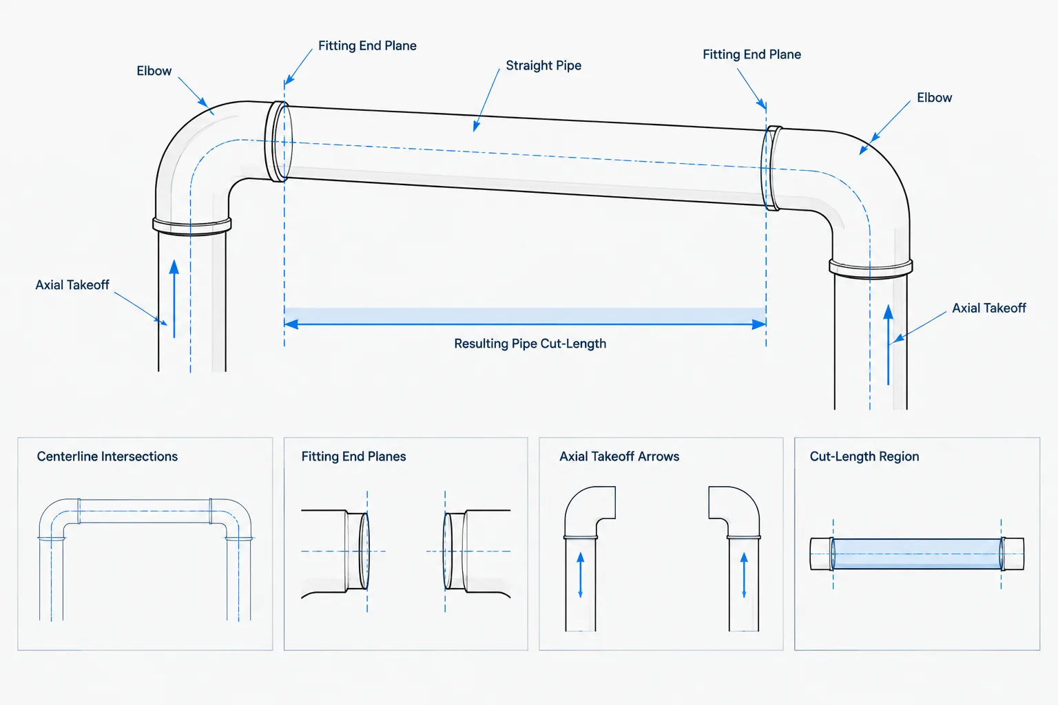
  • Pipe Fitting Takeoff in CAD: From Centerline Dimensions to Pipe Cut Length

    Pipe Fitting Takeoff in CAD: From Centerline Dimensions to Pipe Cut Length

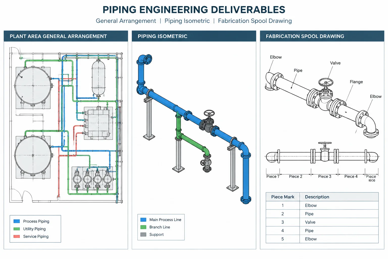
  • Piping General Arrangement Drawings vs. Isometrics vs. Spool Drawings

    Piping General Arrangement Drawings vs. Isometrics vs. Spool Drawings

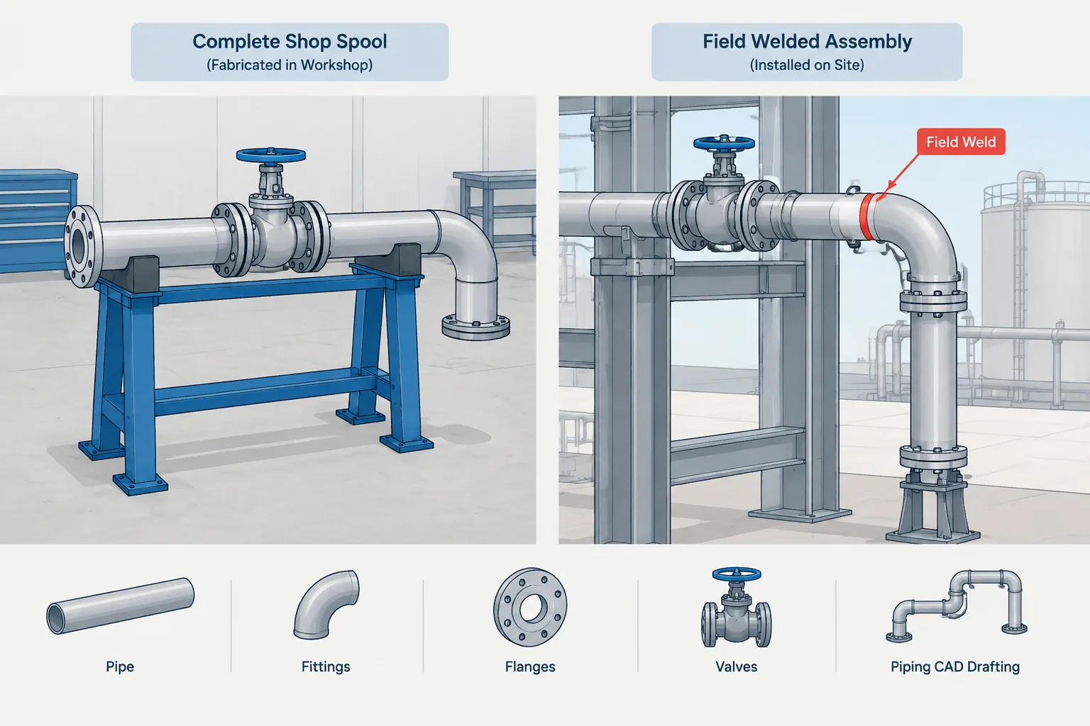
  • Field Weld vs. Shop Weld in Piping CAD: Spool Planning, Location, and Drawing Control

    Field Weld vs. Shop Weld in Piping CAD: Spool Planning, Location, and Drawing Control

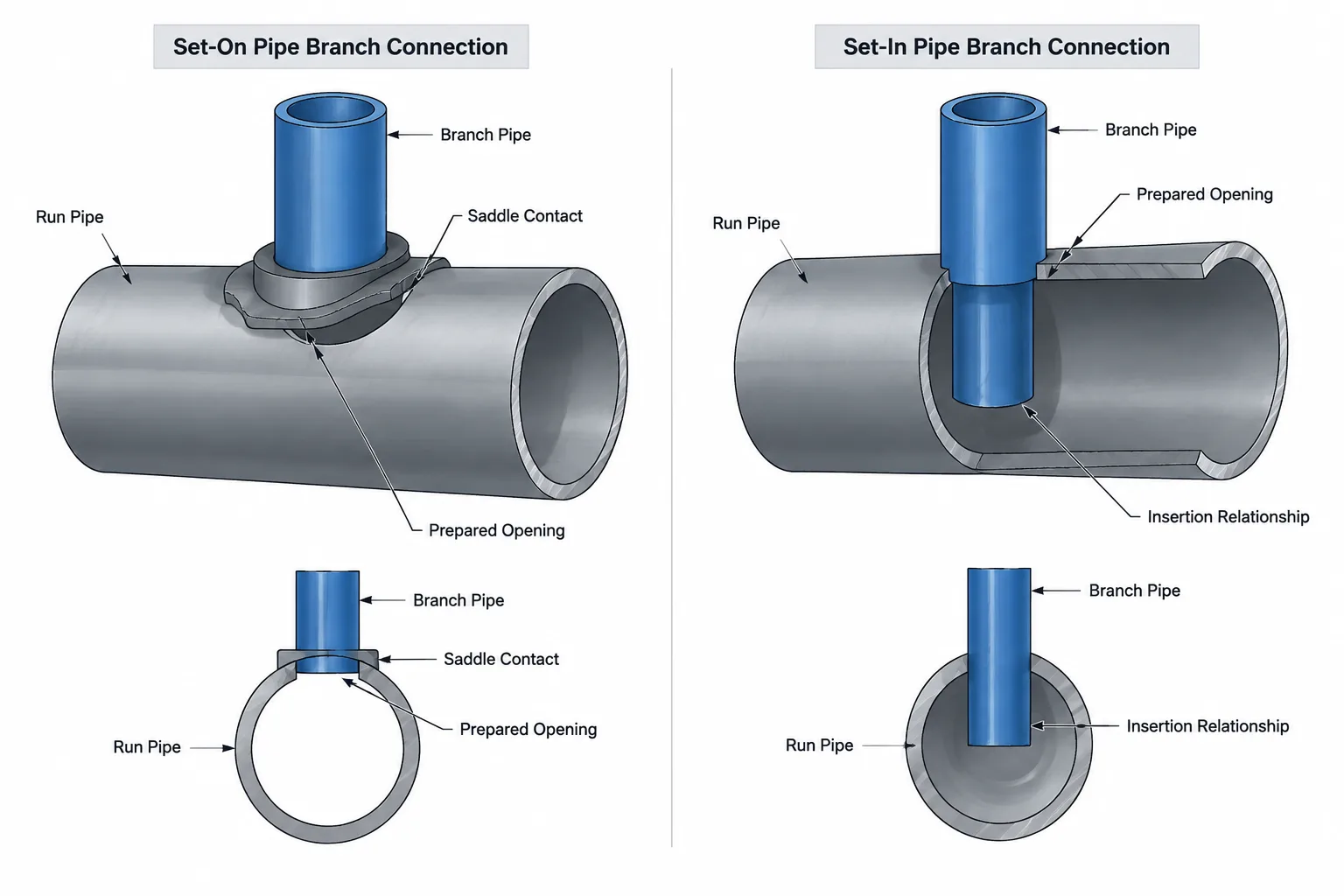
  • Set-On vs. Set-In Pipe Branch Connections: Geometry, Fabrication, and CAD Documentation

    Set-On vs. Set-In Pipe Branch Connections: Geometry, Fabrication, and CAD Documentation