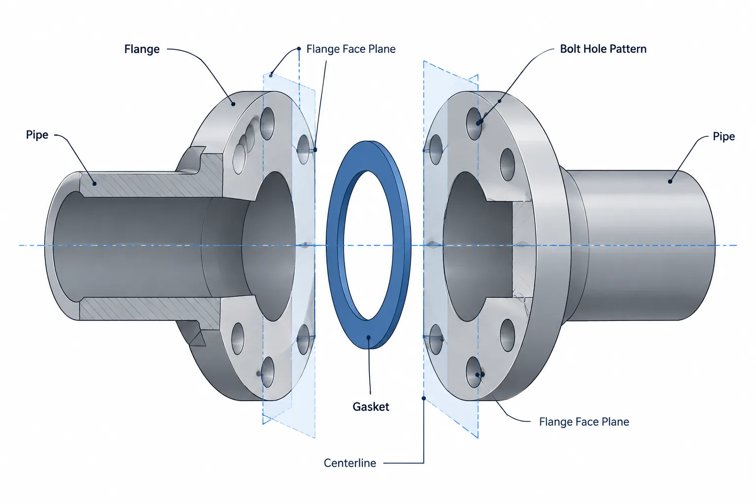
Flange joint alignment in piping CAD requires more than placing two connection points at the same location. A reliable review also considers bore axes, mating face planes, face direction, bolt-hole rotation, joint components, dimensional control, and installation access.
This guide explains how designers and reviewers can distinguish a visually connected model from a joint that has been properly defined for fabrication and field fit-up. It is intended as a practical coordination aid; project specifications, accepted equipment data, inspection requirements, and verified field conditions remain controlling.
A pair of flanges can look connected in a CAD model while still being difficult—or inappropriate—to assemble in the field. Their centerlines may meet, but the faces may not be parallel. Bolt holes may be clocked incorrectly. The connected equipment nozzle may be displaced from its verified location, or the piping may require force to close an unintended gap.
Flange joint alignment in piping CAD is therefore more than a connectivity check. It is a review of mating geometry, dimensional control, installation sequence, and the boundary between nominal design data and actual field conditions. The objective is not to make CAD predict every fabrication variation. It is to produce a layout that can be checked, assembled, and adjusted through an approved fit-up plan rather than by forcing components into place.
What flange alignment actually includes
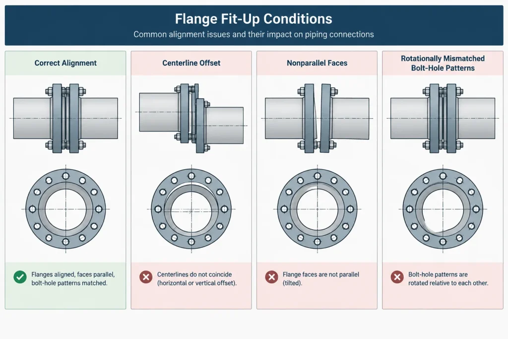
The word alignment can refer to several different conditions. A useful CAD review separates them instead of treating the joint as simply connected or disconnected.
| Alignment condition | What to examine in CAD | Possible field consequence |
|---|---|---|
| Centerline alignment | Whether the axes of the two connecting components are coincident | Offset bores, difficult bolting, or unintended loading during assembly |
| Face position | Whether the mating faces meet at the intended joint plane | Excessive gap, interference, or incorrect spool length |
| Face parallelism | Whether the flange face normals point directly toward one another | A wedge-shaped gap or uneven gasket compression |
| Bore compatibility | Whether the modeled flow passages and connected component sizes are consistent | An internal step, obstruction, or specification conflict |
| Bolt-hole orientation | Whether the hole patterns are rotationally compatible and follow project convention | Bolts that cannot pass through both flanges or inconsistent field orientation |
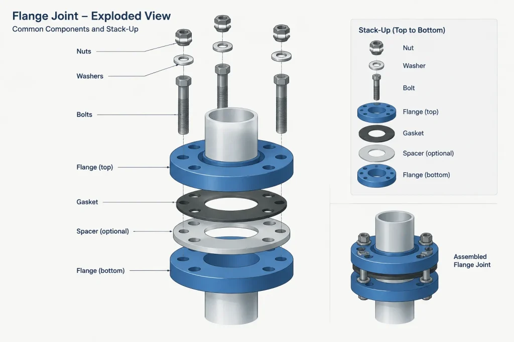
| Joint stack-up | Whether the model accounts for the intended flanges, gasket, specialty items, and connected component | Incorrect cut length or missing joint hardware |
These conditions are related, but one does not prove another. Coincident flange origins, for example, do not establish correct face direction or bolt-hole clocking.
Why nominal CAD geometry can hide fit-up problems
Many piping systems are modeled with ideal centerlines and catalog components. That is appropriate for design, but ideal geometry can conceal the sources of real fit-up difficulty.
- Component ports may connect automatically. A software connection rule may confirm matching nominal ports without evaluating the installation condition.
- Flanges may be simplified. A low-detail component might omit individual bolt holes, gasket thickness, hub geometry, or the actual bore transition.
- Equipment data may be preliminary. A nozzle location based on an early vendor drawing can move before certified information is issued.
- Existing piping may be represented schematically. A point-cloud interpretation or field sketch may not establish the precise face plane and bolt-hole rotation.
- Fabrication and installation variation is not visible. A nominally perfect model does not guarantee that fabricated spools, equipment setting, and supports will arrive in the same positions.
For these reasons, the model should be treated as the controlled nominal arrangement. Applicable codes, project specifications, manufacturer instructions, inspection procedures, and verified field measurements control acceptable fit-up and tolerances.
A practical CAD review workflow
1. Confirm the joint definition
Start by identifying exactly what is being joined. Check the line designation, nominal size, piping specification, flange type, facing, pressure class, material requirements, and connected component. Also determine whether a gasket, isolation kit, spectacle blind, spacer, restriction device, or other item belongs in the joint.
This prevents an apparent alignment problem from distracting attention from a more fundamental component-selection error.
2. Check axis coincidence
Display or construct centerlines through both flange bores. The axes should meet according to the intended design geometry. Review the connection in more than one orthographic direction because an offset can be hidden in a single plan or elevation view.
For a flange on a sloped or skewed run, do not infer alignment from horizontal and vertical dimensions alone. Check the three-dimensional axis and the flange-face normal.
3. Check the mating plane
Verify that the two facing surfaces occupy the intended joint plane. Do not use the overall solid extents or decorative face details as the dimensional reference. Component origins should be tied to a clearly defined connection plane so that replacements and catalog updates do not change the spool geometry unexpectedly.
If the joint contains an inline specialty item, model or otherwise account for its defined end-to-end dimension and connection arrangement. Avoid overlapping solids merely to make the assembly appear closed.
4. Compare face direction
Inspect the face normals or local connection axes. Opposing flange faces should be oriented toward one another. Slight angular errors can be difficult to see in an overall plant view, so use a local section, temporary construction planes, or an exaggerated visual check.
An elbow, skewed branch, or incorrectly rotated custom component can place the flange center at the correct coordinate while leaving its face angularly misaligned.
5. Review bolt-hole clocking
If bolt holes are modeled, compare the two patterns directly. If they are not modeled, verify the flange component’s rotation parameter or local coordinate system. Follow the project’s hole-orientation convention and document exceptions where equipment or specialty-item geometry controls the rotation.
Bolt-hole orientation should not be confused with valve or equipment orientation. Rotating an inline component to improve operator access can also rotate its flange patterns, drain points, or body features.
6. Trace the dimensional chain
Follow the dimensions from a reliable datum to the joint. Determine which items control the final face position: equipment nozzle location, pipe cut lengths, fitting takeouts, valve face-to-face dimensions, gasket accounting, and any field-fit allowance.
A closed chain with no planned adjustment can turn normal installation variation into a flange mismatch. Conversely, an undefined gap is not a substitute for a controlled field-fit strategy.
7. Evaluate assembly access
A geometrically aligned joint may still be unbuildable. Check whether bolts can be inserted and removed, whether tools can reach the fasteners, and whether nearby steel, insulation, valve bodies, or equipment obstruct the work. Consider the assembly sequence rather than reviewing only the completed condition.
Equipment nozzles and existing connections
Flanges at equipment and tie-ins deserve special attention because the piping team may not control both sides of the joint.
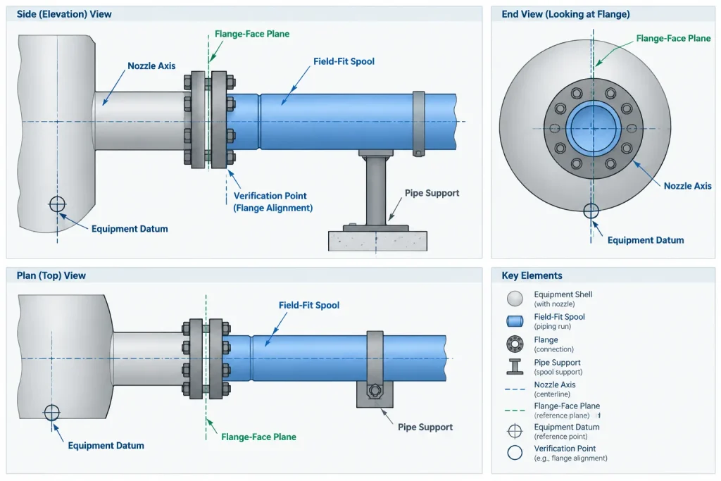
For equipment nozzles, distinguish preliminary data from verified vendor information. Record the nozzle center, projection, orientation, facing direction, and flange rotation using the project’s accepted data source. When information changes, update the connected spool dimensions rather than stretching geometry to preserve an obsolete endpoint.
For existing systems, field verification should capture more than a nominal center point. The survey scope may need to establish the flange-face plane, orientation, bolt pattern, accessible reference coordinates, and surrounding installation constraints. The required survey accuracy and acceptance method should be set by the project team.
Do not use forced fit as a drafting assumption
CAD should not assume that bolts, come-alongs, temporary supports, or pipe flexibility will pull a mismatched joint into position. Drawing two flange faces together does not demonstrate that the resulting loads are acceptable for piping, equipment nozzles, supports, or the gasketed joint.
If an offset or gap is intentional for installation, identify it through an approved note, field-fit spool, closure piece, adjustable support plan, or other project-defined method. If it is unintentional, resolve the geometry and data source instead of hiding the discrepancy.
Useful drawing and model controls
- Use component connection points located at defined flange-face planes.
- Retain local axes or rotation properties that allow bolt-hole orientation to be checked.
- Dimension critical flange faces from stable plant, equipment, or structural datums.
- Identify field welds, closure spools, and field-fit lengths consistently across the model and isometrics.
- Flag flange joints affected by preliminary equipment information or incomplete survey data.
- Coordinate gasketed and specialty-item stack-ups with the bill of materials.
- Use sections or detail views where the overall view cannot show face alignment clearly.
- Avoid implying fabrication precision through excessive drawing decimals unsupported by the source data.
Flange alignment review checklist
Before issuing a model or drawing, reviewers should be able to answer the following questions:
- Are the connected component size, class, facing, and specification data compatible?
- Are the flange axes coincident in three dimensions?
- Do the faces meet at the intended joint plane and point toward one another?
- Is the complete joint stack-up represented or documented?
- Are bolt holes clocked according to the controlling convention or equipment requirement?
- Can bolts and tools access the joint during installation and maintenance?
- Are equipment nozzle coordinates and orientations based on the current accepted data?
- Have existing flange conditions been verified to the level needed for fabrication?
- Is there a defined method for absorbing installation variation?
- Does the isometric dimension chain agree with the coordinated model?
The correct role of CAD
A piping model should establish clear nominal geometry, expose data conflicts, and support a workable fabrication and installation plan. It should not imply that field alignment is guaranteed or that unspecified force may be used to close a joint.
The strongest flange alignment workflow combines accurate connection geometry, controlled dimensions, current equipment data, field verification, and a deliberate fit-up strategy. That approach turns a visually connected model into documentation that fabricators and installers can meaningfully check.
Turning the alignment review into an actionable deliverable
An alignment check is most useful when each discrepancy is tied to a controlling reference and a clear resolution path. A reviewer should be able to determine whether the issue comes from component selection, connection geometry, equipment data, survey information, dimensional chaining, or installation planning.
Separate model errors from unresolved field conditions
A misplaced component origin, reversed face direction, or incompatible flange rotation is a model issue that should be corrected in the design data. An existing connection awaiting survey confirmation is a different condition and should be identified as unresolved rather than adjusted to look correct. Keeping these categories separate prevents nominal geometry from being mistaken for verified field geometry.
Record what controls the joint
The joint record or review markup should identify the accepted datum, the source of the connected equipment or tie-in information, and any item that affects the flange-to-flange stack-up. Where a field-fit method is planned, the model, drawing, isometric, and material documentation should describe the same arrangement consistently.
Review interfaces across disciplines
Flange fit-up can be affected by equipment setting, structural support locations, valve orientation, insulation clearance, and maintenance access. Coordination should therefore include the disciplines responsible for the geometry or constraint rather than treating every mismatch as a piping-model adjustment.
Use CAD as a verification tool, not an acceptance standard
CAD can expose offsets, angular differences, rotation conflicts, missing components, and inaccessible fasteners. It does not establish allowable fabrication or installation tolerances by itself. Acceptance criteria should come from the applicable project requirements and approved technical documents.
Frequently asked questions about flange joint alignment
Does a connected CAD port prove that two flanges will fit?
No. Port connectivity may confirm only that designated connection points or nominal properties match. Face position, face direction, bore alignment, bolt-hole clocking, joint stack-up, and installation access still require review.
Why can flange centerlines match while the faces remain misaligned?
The flange centers can occupy the intended location even when a component has been rotated or its local connection axis has been defined incorrectly. Comparing face normals or local axes helps reveal angular misalignment that may not be obvious in an overall view.
Should bolt holes always be modeled individually?
Not necessarily. The required model detail depends on the design and review purpose. When individual holes are omitted, the component should still retain a dependable rotation reference or parameter so the controlling bolt-hole orientation can be checked.
How should an existing flange tie-in be represented?
Represent it using verified survey information appropriate to the project. If the face plane, orientation, bolt pattern, or surrounding access remains uncertain, identify that uncertainty instead of presenting an idealized connection as field-confirmed.
Can a field-fit allowance replace accurate flange geometry?
No. A field-fit provision is a controlled installation strategy, not a way to hide incorrect or incomplete design geometry. The nominal joint, controlling dimensions, and intended adjustment method should all be clearly documented.
What should be checked when a flange connects to equipment?
Confirm that the model uses the current accepted nozzle location, projection, orientation, facing direction, and flange rotation. Changes to equipment data should be coordinated through the connected piping rather than concealed by stretching or forcing model geometry.