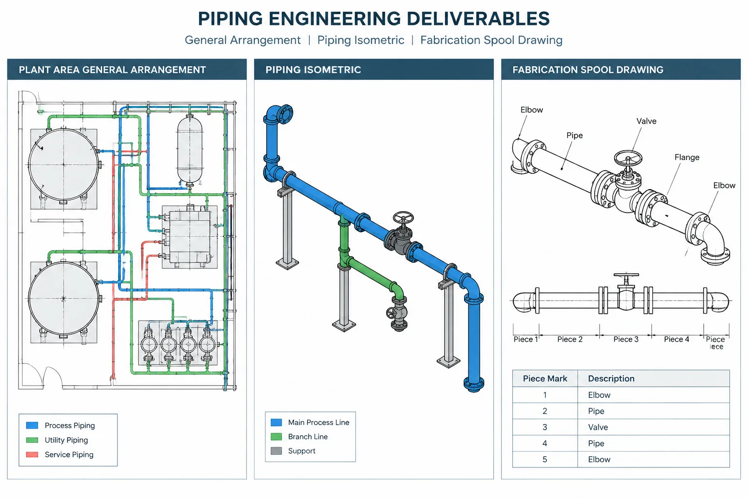
Piping general arrangement drawings, isometrics, and spool drawings may originate from the same design model, but they are not substitutes for one another. Each document presents the system at a different level of context and supports a different stage of design, coordination, fabrication, or construction.
This guide explains how to select the appropriate drawing, interpret its information, and manage discrepancies between related deliverables. The comparison is especially useful when reviewing CAD output, preparing fabrication packages, or tracing a design change through the piping documentation workflow.
A piping model can generate several drawings that appear to describe the same line, yet each deliverable serves a different purpose. General arrangement drawings communicate where piping is located within a plant area. Piping isometrics describe individual lines and their fabrication-related geometry. Spool drawings divide that geometry into manageable fabrication assemblies.
Confusion begins when users treat these drawings as interchangeable. A fabricator may look for weld details on an arrangement drawing, while a layout reviewer may try to assess equipment access from an isolated spool sheet. Understanding what each drawing controls helps designers place information where it is most useful and prevents conflicting dimensions from spreading across the drawing set.
What Is a Piping General Arrangement Drawing?
A piping general arrangement drawing, often called a piping GA, presents piping in the context of equipment, structures, access areas, and neighboring systems. Depending on the project, it may be issued as a plan, elevation, section, or a combination of views.
The primary purpose is spatial coordination. A GA drawing should help the reader understand questions such as:
- Where does the line run relative to equipment and structural elements?
- At what elevation or rack level is the pipe located?
- How does the line enter or leave the drawing area?
- Where are major valves, branches, equipment connections, and supports?
- Can operators and maintenance personnel reach relevant components?
- Does the route conflict with other piping, ductwork, cable systems, or access paths?
A GA drawing may show line numbers, nominal sizes, flow arrows, equipment tags, coordinates, elevations, and selected dimensions. It normally does not need to repeat every fitting takeout, weld location, or pipe cut length. Excessive fabrication detail can make an arrangement drawing difficult to read without improving layout control.
What Is a Piping Isometric?
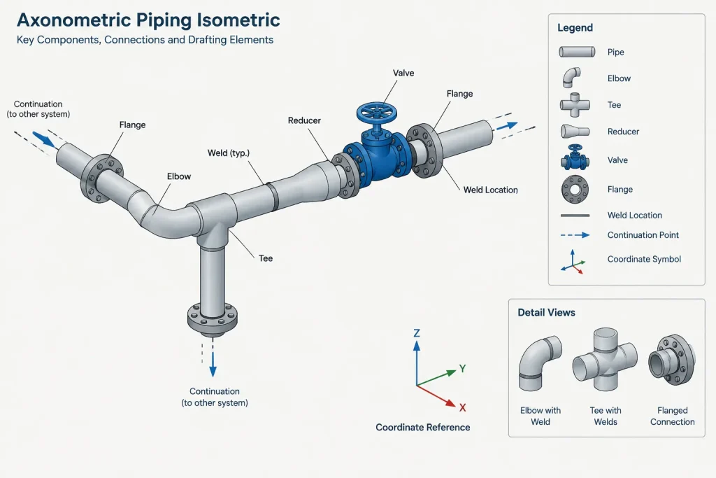
A piping isometric represents a line or defined portion of a line using an axonometric-style view. The view is not a perspective image and generally should not be measured by scaling. Its value comes from dimensions, coordinates, elevations, component callouts, and connection information.

Isometrics translate the coordinated model into a line-focused deliverable. They commonly communicate:
- Pipe routing and direction changes
- Component sequence and orientation
- Branch locations and sizes
- Connection types and joint locations
- Coordinates, elevations, and controlled dimensions
- Line identification and specification information
- Shop and field weld designations when required by the project
- Material takeoff information
- References to supports, equipment nozzles, tie-ins, and continuation drawings
An isometric is more useful for fabrication planning than a GA because it isolates the line and exposes its joint sequence. However, it may still include more than one shop spool, field-installed section, or construction stage. It should not automatically be assumed to be a spool drawing.
What Is a Spool Drawing?
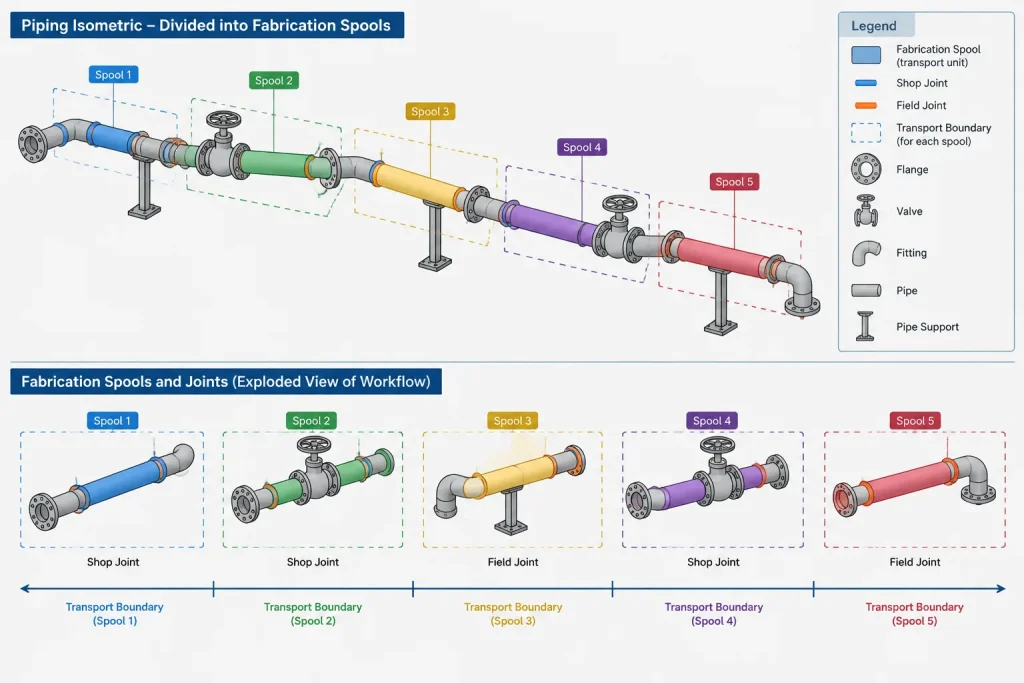
A spool drawing describes a prefabricated piping assembly rather than an entire process line. The spool boundaries are selected according to fabrication, handling, transport, coating, inspection, installation, and field-fit considerations.
A spool can contain pipe, fittings, flanges, branch components, and other items that are assembled before installation. The drawing focuses on information needed to build and identify that particular assembly. Depending on the fabrication workflow, it may include piece marks, cut lengths, weld identifiers, bill-of-material items, orientation references, and inspection data fields.
Spool drawings are downstream fabrication documents. They should be derived from controlled design information, but their organization may reflect shop practices that are not visible in the design model. For example, a fabricator may divide a design isometric into multiple spools to suit shipping or assembly constraints. That subdivision should not change the intended installed geometry.
Comparison of the Three Drawing Types
| Drawing type | Primary purpose | Typical scope | Main users | Information emphasis |
|---|---|---|---|---|
| General arrangement | Plant layout and coordination | An area, unit, rack, or equipment group | Designers, engineers, construction planners, and reviewers | Location, elevation, clearance, access, and interfaces |
| Piping isometric | Line definition and construction communication | A line or a defined section of a line | Designers, material teams, fabricators, inspectors, and construction personnel | Routing, components, joints, dimensions, and material information |
| Spool drawing | Shop fabrication of a specific assembly | One identified fabrication spool | Fabricators, welders, inspectors, and material-control personnel | Piece geometry, cut information, welds, item identity, and assembly orientation |
Which Drawing Controls a Dimension?
No drawing type automatically controls every dimension. Dimension ownership should be established by the project’s document hierarchy, specifications, drawing procedures, and issue status. The design model may be the primary source for geometry, while approved vendor information may control equipment interfaces. Fabrication drawings may add shop-specific detail without having authority to relocate a nozzle or alter a piping route.
As a practical rule, each dimension should appear where it supports the intended task:
- GA dimensions should establish major plant locations, routing corridors, elevations, equipment relationships, and significant interfaces.
- Isometric dimensions should define the installed line geometry and provide sufficient information to interpret offsets, branches, and connection locations.
- Spool dimensions should support fabrication of the identified assembly, including piece-level information generated from the controlled design.
Repeating the same dimension on several drawings creates a coordination obligation. If the route changes, every repeated value must be updated and checked. Where duplication is necessary, drawing-generation and revision workflows should make the common source clear.
Model-Derived Geometry Does Not Eliminate Drawing Checks
Automatic drawing extraction can improve consistency, but it does not determine whether the resulting document is understandable. A model may contain accurate component ports while an isometric displays crowded dimensions, ambiguous continuations, or an unreadable branch orientation. A spool drawing may calculate a pipe piece from modeled endpoints but still fail to explain a required rotational relationship.
Drawing checks should therefore address both geometric accuracy and communication quality. Useful review questions include:
- Do tags and line numbers agree across the model, GA, isometric, and spool documents?
- Are coordinates and elevations referenced to the correct project datum?
- Are continuation points uniquely identified?
- Can the orientation of eccentric components, branches, valves, and flanges be understood?
- Are field joints and spool boundaries consistent with the installation plan?
- Does the material list match the components actually shown?
- Are revised items distinguishable under the project’s revision procedure?
Managing Changes Across the Drawing Set
A layout change often affects more than one deliverable. Moving a pipe on a GA can alter isometric dimensions, support locations, spool geometry, material quantities, and field-weld positions. Conversely, a shop proposal to move a weld may affect only the spool division, or it may interfere with a support, branch, or installation sequence.
Changes should be classified before documents are revised. A design geometry change must return to the controlled design source. A fabrication subdivision change may be handled in the spool workflow if it does not alter installed geometry or violate project requirements. Field changes require verification and eventual incorporation into the appropriate as-built records.
Marking up a single drawing without evaluating related documents is a common source of inconsistency. The safest workflow uses a defined source of truth, a change log or revision process, and a check of all affected outputs.
A Practical Drawing-Use Workflow
Start with the GA for context
Use plans, elevations, and sections to review routing, equipment relationships, operating access, maintenance space, and area interfaces. Do not rely on an isolated isometric to reveal every surrounding obstruction.
Use the isometric to understand the line
Trace component sequence, branches, elevations, offsets, connections, and drawing continuations. Confirm that the line-level information agrees with the P&ID, line data, piping specification, and model.
Use the spool drawing for fabrication detail
Review the exact assembly identity, piece information, weld sequence, orientation references, and material items. Confirm that spool boundaries correspond to the approved fabrication and installation strategy.
Resolve discrepancies through document control
Do not choose a convenient value simply because it appears on the most detailed-looking drawing. Check issue status, governing project procedures, approved interface data, and the source model. Record and resolve the discrepancy before fabrication or installation proceeds.
Why the Distinction Matters
GA drawings, isometrics, and spool drawings are related views of the same piping system, but they answer different questions. The GA explains where the piping belongs. The isometric explains how the line is configured. The spool drawing explains how a particular shop assembly is to be built and identified.
Keeping those roles clear produces cleaner drawings, reduces duplicated dimensions, and makes revisions easier to control. It also helps each user find the right level of information without expecting one document to replace the entire piping design and fabrication record.
Document Status Matters as Much as Drawing Type
A drawing title identifies its intended function, but it does not establish whether the document is approved for the task at hand. A fabrication-focused sheet can still be preliminary, while an arrangement drawing may be the current approved reference for a controlled interface. Reviewers should confirm issue status, revision, approval purpose, and applicable project procedures before relying on any drawing.
This distinction is important when files circulate outside the original document-management system. A clearly detailed spool sheet may appear authoritative even though a later design revision has changed the installed route. Likewise, a current isometric does not automatically validate an older spool drawing derived from an earlier geometry state.
Recommended Cross-Document Handoff Checks
Before releasing related piping documents to another discipline, a fabricator, or the field, verify that the handoff preserves both geometry and identification. The review should consider:
- Whether line, equipment, valve, support, and connection identifiers remain consistent
- Whether drawing continuations lead to the correct companion documents
- Whether equipment interfaces reflect the approved source information
- Whether spool boundaries preserve the intended installed geometry
- Whether field-fit and field-weld decisions agree with the construction strategy
- Whether changed components are reflected in associated material information
- Whether superseded outputs have been removed from active use
The objective is not to force every drawing to contain the same information. It is to ensure that each deliverable communicates its assigned scope without contradicting the controlled design source.
Choosing the Right Drawing for a Review
Use the drawing that matches the decision being made. Area routing, access, and multidisciplinary interfaces belong primarily in the arrangement review. Line geometry, component sequence, and connection definition belong in the isometric review. Piece fabrication, weld identification, and assembly orientation belong in the spool review.
When a decision crosses these boundaries, consult the related documents rather than expanding one sheet until it attempts to perform every function. This keeps the drawing set readable and makes responsibility for revisions easier to trace.
Frequently Asked Questions
Is a piping isometric the same as a spool drawing?
No. An isometric defines a line or a selected part of a line, while a spool drawing defines a particular prefabricated assembly. One isometric may support multiple fabrication spools.
Can a general arrangement drawing be used for pipe fabrication?
A GA drawing provides valuable routing and interface context, but it normally does not contain all piece-level fabrication information. Fabrication should use the documents approved for that purpose under the project workflow.
Which drawing should be used to check plant access and clearances?
General arrangement plans, elevations, and sections are usually the most useful starting point because they show piping in relation to equipment, structures, and surrounding systems. The model and relevant discipline documents may also be required for a complete review.
Which document takes precedence when drawings disagree?
Precedence depends on the project document hierarchy, issue status, specifications, approved interface information, and change-control procedure. The most detailed-looking drawing should not be assumed to govern automatically.
Can a fabricator change spool boundaries without changing the piping design?
A fabrication subdivision may be adjusted when the controlled workflow permits it and the installed geometry, interfaces, support relationships, and project requirements remain unaffected. The change should still be reviewed and documented.
Should the same dimensions appear on every related drawing?
Not necessarily. Dimensions should be placed where they support the intended use of each document. Repeating a dimension creates an additional revision and coordination obligation whenever the design changes.