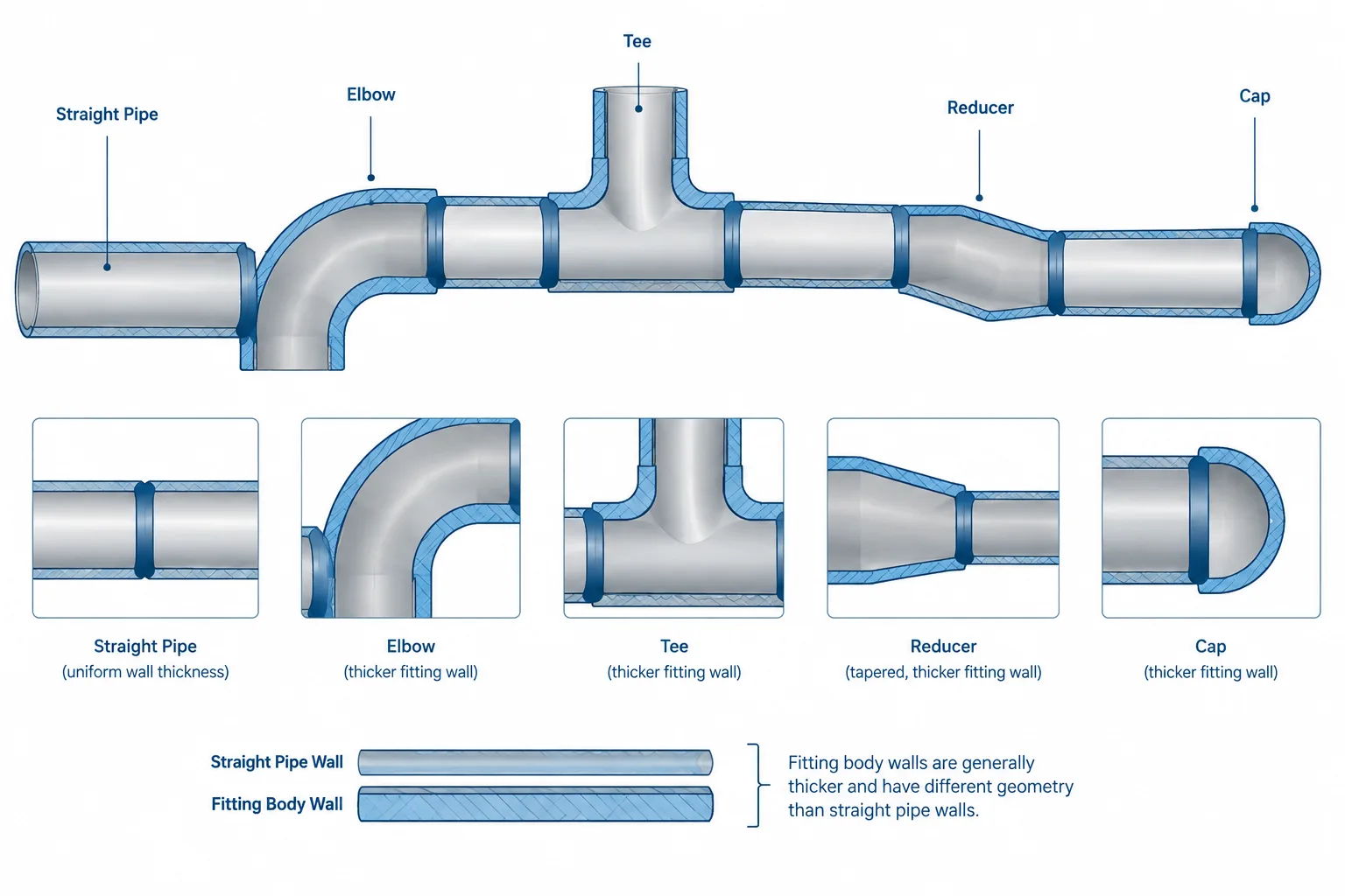
Do pipe fittings have a schedule? Some do, particularly butt-welding fittings described in relation to the wall of adjoining pipe. However, schedule is not a universal fitting designation, and it does not mean that the fitting has the same wall thickness throughout its formed body.
The correct interpretation depends on the fitting family, material specification, end connection, product requirements, and project piping specification. The discussion below explains how schedule applies to fitting ends, why fitting geometry complicates wall-thickness assumptions, and what should be checked during specification, procurement, and CAD modeling.
Pipe schedule is commonly associated with straight pipe, but schedule designations also appear in descriptions of many butt-welding fittings. This can create a misleading impression that every fitting follows the same schedule system or that a fitting marked with a particular schedule has an identical wall thickness at every point.
In practice, fitting terminology depends on the product type, end connection, material specification, and governing product standard. A schedule description may identify the pipe wall with which a fitting is intended to be used, but it does not replace verification of the fitting standard, material, end preparation, pressure design, and project piping specification.
What pipe schedule means for straight pipe
For straight pipe, the nominal pipe size and schedule work together to identify a listed nominal wall thickness. For a given nominal pipe size, changing the schedule generally changes the wall thickness and inside diameter while leaving the standardized outside diameter unchanged.
Schedule is therefore not a material grade, pressure class, or universal thickness. The wall associated with a schedule depends on pipe size, and the resulting pressure capability also depends on material, temperature, allowances, manufacturing rules, and the applicable design code.
This distinction matters when a designer moves from pipe data to fitting data. A fitting must connect to the pipe, but its shape and local wall distribution are not the same as those of a straight cylindrical pipe.
When a fitting may be described by schedule
Schedule terminology is most commonly encountered with butt-welding fittings such as elbows, tees, reducers, and caps. A purchase description or piping material specification may call for a fitting that corresponds to the wall designation of the adjoining pipe.
In this context, the schedule helps communicate the intended end-wall relationship. It allows the fitting ends to be prepared for welding to the specified pipe wall without treating the fitting as an unrelated pressure class item.

However, the complete fitting description normally requires more than a schedule. Depending on the product and project, relevant information may include:
- fitting type and configuration;
- nominal end sizes and branch size, where applicable;
- long-radius, short-radius, reducing, or other geometry;
- material specification and grade;
- seamless or welded construction when that distinction is controlled;
- wall or schedule designation;
- end preparation requirements;
- dimensional and product standard;
- special examination, heat treatment, or supplementary requirements.
A schedule callout should therefore be read as one field in the component definition, not as a complete specification.
Why fitting wall is not uniform like straight pipe wall
A butt-welding fitting changes the direction, size, or distribution of flow. Its body may be formed, forged, pressed, drawn, or fabricated through a process appropriate to the product. The resulting geometry can include curved regions, crotch areas, transitions, and closed ends.
Because of this geometry, the wall through the fitting body is not adequately described by imagining a constant pipe wall swept through the fitting. Forming can change local thickness, and product design rules may require material distribution suited to the fitting shape.
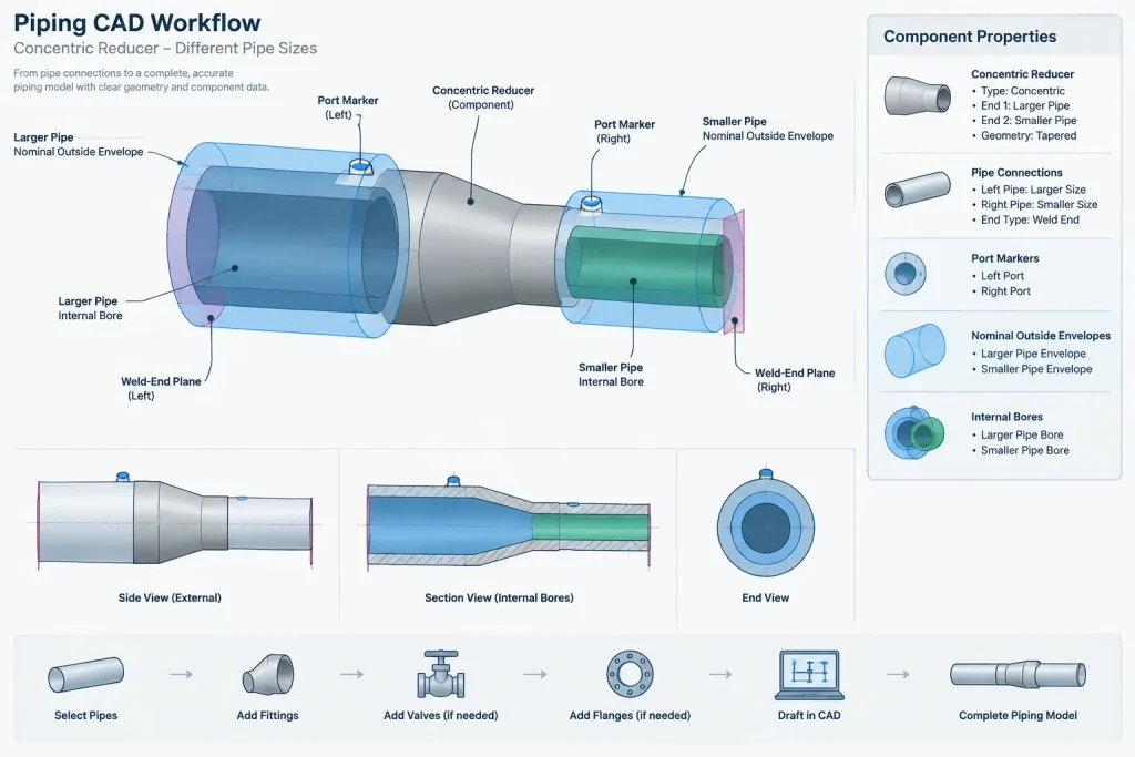
The wall at a weld end is especially important because it interfaces with the adjoining pipe. The wall elsewhere in the fitting body may differ from that end wall. A generic CAD model often represents only the nominal outside envelope and a simplified bore, so it should not be used to infer minimum local wall or manufacturing compliance.
Elbows
An elbow has an inside curve and an outside curve rather than a uniform straight-pipe section. Its dimensional standard controls key envelope geometry, while the applicable product requirements govern matters such as wall and end configuration. A model built by sweeping a constant annular profile may be useful for layout, but it is not necessarily a manufacturing representation.
Tees
A tee includes a branch intersection and crotch region. An equal tee has matching nominal run and branch sizes, while a reducing tee has different end sizes. Schedule terminology alone does not explain how material is distributed around the branch intersection.

Reducers
A reducer connects two nominal pipe sizes, so both ends must be considered. A project description may establish the wall designation intended at each end, but users should not assume that one casual schedule label fully defines every reducing fitting configuration. The transition body also should not be modeled as a constant-thickness cone unless that level of simplification is appropriate for the task.
Caps
A cap has an open weld end and a formed closed end. The weld-end relationship can be coordinated with the pipe schedule, while the crown geometry and local wall behavior are characteristics of the fitting product rather than straight pipe.
Not every fitting uses schedule terminology
Schedule is not the universal rating language for all fittings. Forged socket-weld and threaded fittings are commonly organized using class designations under their applicable product system. Other fitting families may use pressure ratings, dimensional series, tubing wall terminology, or manufacturer-specific product descriptions.
These systems must not be treated as interchangeable. A forged fitting class is not another way of writing a pipe schedule, just as flange class is not a pipe schedule. The adjoining pipe still needs its own size, wall, material, and end definition.
| Component family | Common controlling description | Key caution |
|---|---|---|
| Butt-welding elbows, tees, reducers, and caps | Nominal size, fitting type, material, and wall or schedule designation | Schedule does not describe the complete fitting body geometry |
| Socket-weld forged fittings | Nominal size, fitting type, material, and fitting class | Fitting class and pipe schedule are different data fields |
| Threaded fittings | Nominal size, thread form, material, and applicable class or rating system | Thread compatibility and engagement require separate control |
| Flanged fittings | Nominal size, flange class, facing, material, and configuration | Flange class does not directly specify connected pipe wall |
| Proprietary or specialty fittings | Manufacturer and project-defined product data | Do not substitute generic dimensions without verification |
Matching a butt-welding fitting to pipe
The practical objective is a weld-end transition that satisfies the engineering design and fabrication requirements. A matching nominal size establishes the general outside-diameter interface, but it does not by itself guarantee a matching bore or wall.
Designers should check the following:
- Nominal size: Confirm each run and branch end, especially for reducing tees and reducers.
- Pipe wall: Identify the selected pipe schedule or specified nominal wall for every connected segment.
- Fitting wall designation: Confirm how the project specification defines the corresponding fitting.
- Material and product form: Verify that the fitting material description is appropriate and complete.
- End preparation: Coordinate bevels, land, bore preparation, and any required transition detail with fabrication requirements.
- Bore mismatch: Evaluate unequal inside diameters rather than assuming that matching outside diameters create a smooth internal joint.
- Allowances and minimum wall: Keep design allowances and procurement requirements separate from nominal CAD geometry.
Heavy-wall connections deserve particular attention. A standard-looking external envelope can conceal a significant bore difference, and a simplified CAD symbol may not reveal whether special end preparation or internal transition work is required.
How to represent fitting wall in CAD
The appropriate representation depends on the purpose of the model. For routing and interference checking, an accurate external envelope, center-to-end dimensions, connection points, and required clearances may be more valuable than a detailed internal wall model.
For fabrication-oriented work, the bore and weld-end relationship can become important. Even then, the model should distinguish nominal representation from verified manufacturing data.
A practical component record may include separate properties for:
- nominal size at each port;
- connected pipe schedule or wall;
- fitting wall designation;
- material specification and grade;
- end connection and end preparation;
- component standard or catalog source;
- commodity or specification code;
- model status, such as generic, catalog-based, or vendor-specific.
Avoid encoding all of this information into one ambiguous name. For example, a block name containing only size and schedule may omit the fitting type, material, radius, branch size, or source of its dimensions.
Common specification and drafting mistakes
- Applying schedule to every fitting family: This confuses butt-welding fitting terminology with class-based or rating-based products.
- Assuming schedule is a pressure rating: Pressure suitability cannot be established from schedule alone.
- Using the run schedule for every reducer end: Both connected pipe segments must be checked.
- Modeling a constant wall through a formed fitting: This may be visually convenient but should not be presented as verified internal geometry.
- Ignoring the piping material specification: A generic fitting table cannot resolve project-specific material, construction, examination, and end-preparation requirements.
- Taking dimensions from an unverified CAD block: Connection locations and envelopes should be checked against the controlled dimensional source.
A better interpretation of “matching schedule”
When a butt-welding fitting is said to match the pipe schedule, interpret the phrase as an instruction to coordinate the fitting weld ends with the adjoining pipe wall under the applicable specification system. Do not interpret it as proof that the entire fitting has a uniform wall identical to straight pipe.
The safest workflow is to identify the component family first, determine whether schedule is the correct designation for that family, and then verify size, material, ends, dimensions, and project requirements independently. This approach produces clearer material specifications, more reliable CAD data, and fewer surprises during procurement and fabrication.
A practical review sequence for fitting selection
Schedule should be evaluated within the full component definition rather than used as the starting and ending point of selection. A disciplined review helps prevent a familiar schedule label from obscuring differences in fitting type, construction, material, or end configuration.
- Identify the component family: Determine whether the item is a butt-welding, socket-weld, threaded, flanged, or specialty fitting.
- Define every connection: Record the nominal size and connected pipe wall at each run, branch, or reducing end.
- Confirm the designation system: Establish whether the fitting is described by schedule, wall, class, rating, or controlled manufacturer data.
- Check the product definition: Verify fitting geometry, material, construction, dimensional source, and any project-specific requirements.
- Review the weld interface: Compare the fitting end and pipe bore rather than relying only on matching nominal size or outside diameter.
- Control the CAD representation: State whether the model is generic, catalog-based, or vendor-specific, and avoid implying that simplified internal geometry represents manufactured wall distribution.
Information to communicate at design handoff
A clear handoff separates what has been selected from what still requires confirmation. The component record, material takeoff, or purchase description should make the fitting family and connection requirements unambiguous. Fabrication-sensitive details should remain tied to the controlled piping specification and approved product data.
If the available model shows only an external envelope, that limitation should be visible to downstream users. Likewise, a schedule included in a component name should not be treated as evidence that material, pressure suitability, end preparation, or local fitting wall has been verified.
Frequently asked questions
Do all pipe fittings have a schedule?
No. Schedule terminology is commonly associated with straight pipe and many butt-welding fittings. Other fitting families may be organized by class, rating, thread system, tubing wall description, or manufacturer-defined product data.
Does a fitting schedule mean the entire fitting has the same wall as the pipe?
No. The designation generally helps coordinate the fitting weld end with the adjoining pipe wall. Formed regions, curves, branches, transitions, and closed ends cannot be assumed to have a uniform straight-pipe wall.
Is pipe schedule a pressure rating for the fitting?
No. Schedule alone does not establish pressure suitability. Material, temperature, design allowances, product requirements, and the applicable piping design rules must also be considered.
Will matching nominal size and schedule guarantee equal bores?
Not by themselves. Designers should compare the connected pipe wall, fitting end configuration, bore, and required weld transition. This is especially important where different walls or reducing ends are involved.
How should schedule be handled for a reducer?
Each reducer end should be coordinated with the pipe segment it connects to. A single informal schedule description should not be assumed to define both ends or the wall through the transition body.
Can a generic CAD fitting be used to verify wall thickness?
Not unless its internal geometry is supported by controlled product data. Generic models are often intended for routing, connection placement, and clearance checking rather than verification of local manufactured wall.