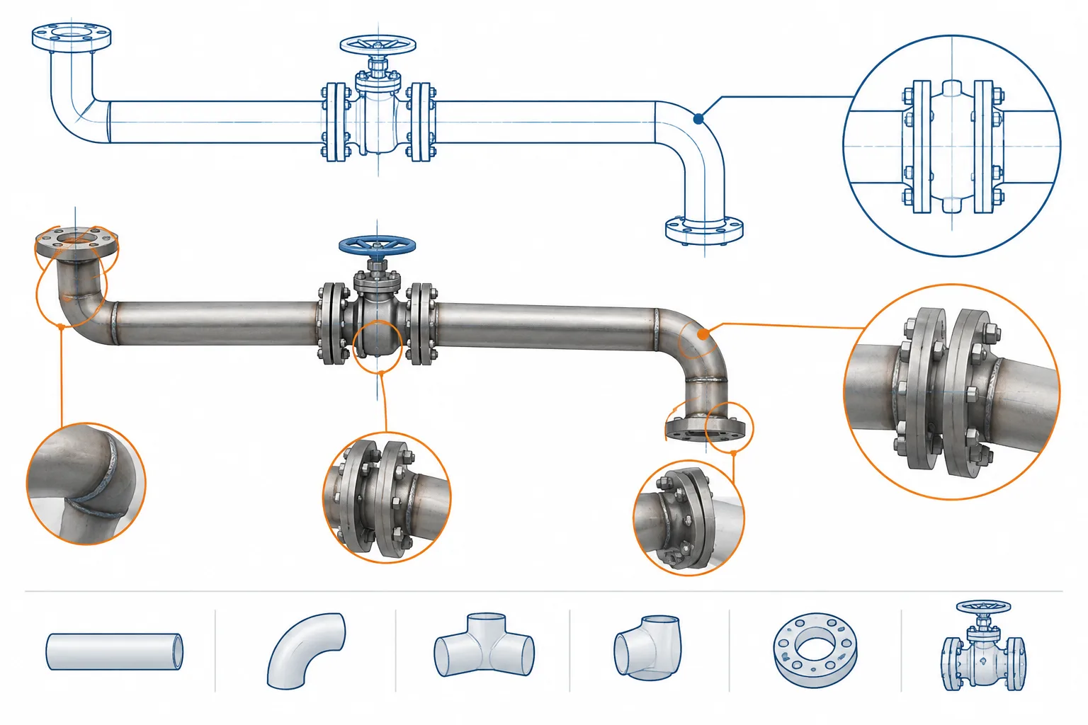
CAD precision and fabrication tolerance are not interchangeable. A piping model defines the intended geometric relationship between components, but fabrication and installation involve manufactured parts, joint preparation, welding, surveys, structures, and equipment that may not occupy their nominal positions exactly.
This distinction matters most at fixed interfaces, field tie-ins, equipment nozzles, penetrations, and prefabricated assemblies. The following guide explains how to interpret model accuracy, identify fit-sensitive connections, and produce drawings that communicate what controls fabrication without implying unrealistic certainty.
A piping model can place every component at an exact coordinate, yet the fabricated system may not assemble exactly as modeled. This is not necessarily a modeling failure. CAD geometry is mathematically precise, while real pipe, fittings, welds, equipment, structures, and field measurements all have allowable or unavoidable variation.
The practical goal is not to make the model imitate every possible deviation. It is to identify which dimensions control function and fit, use verified component data where needed, and provide a workable plan for absorbing variation. Understanding the difference between CAD precision and physical tolerance helps designers avoid false confidence, unnecessary dimensions, and difficult field fit-up.
CAD precision and physical tolerance are different concepts
CAD software represents geometry using defined coordinates, angles, radii, and connection points. If two modeled pipe ends share an axis and endpoint, they meet perfectly in the model. Real components do not behave with the same mathematical certainty.
Physical variation may come from pipe outside diameter and wall variation, fitting geometry, flange facing, weld shrinkage, cutting, forming, equipment placement, structural erection, measurement uncertainty, and installation sequence. The applicable limits may be established by a product standard, fabrication specification, project requirement, manufacturer, or construction procedure.
Modeling additional decimal places does not reduce those physical variations. Display precision is mainly a drafting and data-presentation choice; it is not evidence that a dimension can be fabricated or measured to the same resolution.
Where piping variation enters the assembly
Manufactured components
Standardized fittings and flanges are generally selected by nominal designation, but an individual component may vary within its permitted manufacturing limits. A generic CAD component often represents nominal geometry rather than the measured shape of the item delivered to the shop.
Manufacturer-specific dimensions become especially important for valves, strainers, specialty items, actuators, lined components, expansion joints, and other equipment whose envelope or connection geometry cannot safely be inferred from a generic symbol or nominal size.
Pipe cutting and end preparation
Pipe cut length can be affected by the measuring method, cut squareness, bevel preparation, thermal cutting, machining, and how the fabricator interprets the controlling drawing dimensions. A model may show a single exact endpoint even though the shop must create a physical end suitable for the specified joint.
Welding and assembly
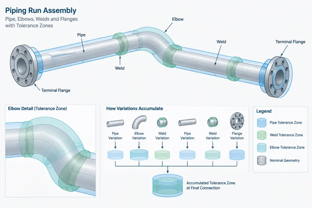
Fit-up gaps, weld sequencing, heat input, restraint, and distortion can change the final position or rotation of an assembly. Small deviations across several joints may accumulate into a noticeable mismatch at a terminal flange or tie-in point.
Equipment and structural placement
Piping is often modeled from design coordinates for equipment nozzles, pipe racks, platforms, walls, and supports. The installed positions of those interfaces may differ from design coordinates. Baseplate setting, structural erection, grout, nozzle orientation, and survey control can all affect the actual connection location.
Field measurement
A field dimension is not automatically an exact dimension. Its reliability depends on the datum, instrument, access, line of sight, temperature, reference geometry, and whether insulation or existing attachments obstruct the measurement. A measurement should be traceable to clearly identified points rather than described only as a distance “from the pipe” or “from the wall.”
Nominal, reference, and controlling dimensions
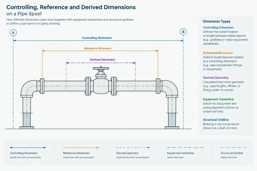
Not every dimension on a piping drawing has the same purpose. Separating dimension types makes the deliverable easier to interpret and reduces conflicts.
| Dimension type | Primary purpose | Typical treatment |
|---|---|---|
| Nominal design dimension | Defines intended routing or arrangement | Used for layout unless replaced by verified interface data |
| Reference dimension | Provides convenience or context | Identified as non-controlling and checked against controlling geometry |
| Controlling fabrication dimension | Directs the size or location that must govern shop work | Shown from stable, unambiguous datums |
| Field-verified dimension | Records an existing or installed condition | Associated with survey status, date, source, or verification note |
| Derived dimension | Results from other controlled coordinates or geometry | Usually not independently toleranced or used to close another dimension chain |
A common drafting problem occurs when several dimensions attempt to control the same geometry from different directions. If rounding, revisions, or component substitutions create disagreement, the drawing contains a closed dimension loop. The fabricator then has to decide which value governs. A better approach is to establish a clear datum system and identify only the dimensions required to manufacture and inspect the spool.
Tolerance accumulation across a piping run
Variation can accumulate when a spool contains multiple fittings, welds, and pieces of pipe. The final connection position is influenced by the combined assembly, not merely by the tolerance of one part.
This issue is particularly important where a run terminates between fixed interfaces, such as two equipment nozzles, an existing line and a vessel connection, or two independently erected structures. A model may close perfectly between the design coordinates while leaving no practical means to absorb actual field variation.
Designers should review the chain of interfaces and ask:
- Which endpoints are truly fixed?
- Which interface dimensions are verified and which remain preliminary?
- Can a component rotate or shift during assembly?
- Is there a field-adjustable segment or closure spool?
- Does the joint type permit useful adjustment?
- Is field measurement required before final fabrication?
- Could accumulated angular error create flange misalignment?
The answer is not to assign arbitrary tolerances in the CAD file. Tolerances must come from the governing project documents, applicable standards, fabrication practices, and engineering requirements. The CAD review should instead reveal where tolerance decisions and fit-up planning are necessary.
Use functional requirements to set modeling priorities
Some geometric relationships matter more than the exact appearance of the component body. Functional interfaces deserve the greatest attention.
- Flanged joints: Face location, axis, rotation, bolt-hole orientation, gasket space, and assembly access may control successful fit-up.
- Butt-weld joints: Centerline alignment, end location, bore transition, and end preparation may be more important than detailed weld-bevel graphics.
- Socket-weld and threaded joints: Engagement assumptions and assembly sequence affect cut length and replaceability.
- Equipment nozzles: Connection face, orientation, projection, and allowable interface loads require verified equipment information.
- Supports: Contact elevation, support type, movement direction, and attachment location can matter more than decorative support detail.
- Maintenance items: Removal paths and access envelopes should account for installed surroundings, not only nominal body geometry.
This priority-based approach keeps the model useful without implying that every modeled surface represents surveyed or manufacturer-certified geometry.
A practical CAD and drawing workflow
1. Establish reliable datums
Use project coordinates, equipment centerlines, structural grids, established elevations, or surveyed control points as appropriate. Avoid dimension chains based on temporary objects or poorly defined edges.
2. Classify interface data
Mark nozzle locations, existing-pipe coordinates, vendor dimensions, and structural openings according to their status. Preliminary and assumed information should not look identical to verified information.
3. Model nominal geometry consistently
Build routing from controlled centerlines and connection points. Use verified component dimensions when the physical envelope or end-to-end length affects layout. Do not alter a component merely to make an unresolved interface appear to fit.
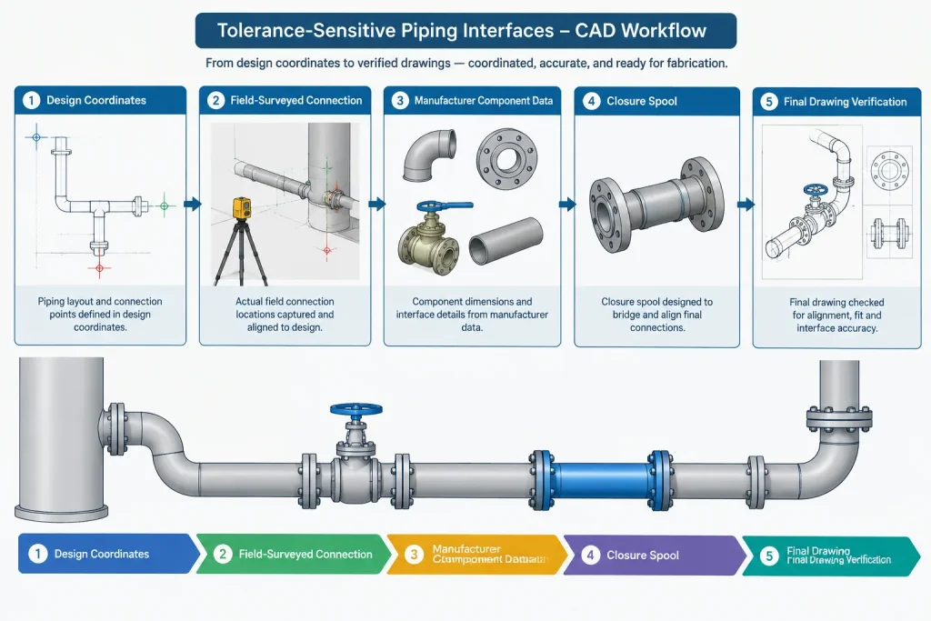
4. Identify tolerance-sensitive closures
Review runs between fixed endpoints, tie-ins, flanged equipment connections, penetrations, and prefabricated modules. Decide where field verification, adjustment, or delayed fabrication may be appropriate.
5. Dimension from functional datums
Control spool geometry with a clear hierarchy of coordinates, centerlines, face locations, and elevations. Minimize redundant dimensions and clearly distinguish reference values.
6. Coordinate revisions across deliverables
A changed nozzle location may affect the 3D model, isometric, spool drawing, support arrangement, bill of materials, and clash review. Updating only the visible pipe route can leave inconsistent fabrication information elsewhere.
7. Verify before release
Check that model connections, drawing dimensions, component records, and field data agree. Confirm that any project-specific tolerance notes have been reviewed by the responsible engineering and fabrication disciplines.
Common mistakes to avoid
- Assuming a visually connected model guarantees physical fit-up.
- Using excessive decimal precision to imply fabrication accuracy.
- Treating generic valve or specialty-item geometry as manufacturer-certified data.
- Closing a run between unverified equipment or field coordinates.
- Adding redundant dimensions that independently control the same endpoint.
- Hiding an interface discrepancy by stretching a fitting or scaling a CAD block.
- Applying a general tolerance note without checking whether specific dimensions require different control.
- Ignoring angular and rotational variation while checking only linear distances.
Precision should support constructability
An exact model remains essential for coordination, interference checking, material extraction, and drawing production. Its value is greatest when users understand what the geometry represents: usually the intended nominal arrangement, supplemented by verified interface and manufacturer data where required.
Good piping documentation does not promise impossible perfection. It defines stable datums, identifies controlling dimensions, distinguishes verified data from assumptions, and provides a plan for locations where real-world variation must be measured or accommodated. That is how CAD precision becomes useful fabrication information rather than a false guarantee of fit.
Turn model accuracy into an interface-control plan
A useful model should make uncertainty visible rather than conceal it. Each critical connection can be reviewed in terms of its datum, information source, verification status, controlling geometry, and available method of adjustment. This turns a general concern about tolerance into specific decisions that engineering, drafting, fabrication, surveying, and construction teams can resolve.
Separate geometry status from drawing precision
A neatly displayed coordinate may still be based on preliminary vendor information, an assumed structural location, or an inaccessible field measurement. Conversely, a verified interface does not need excessive displayed precision to be authoritative. Status and source should therefore be communicated independently from the number format used on a drawing.
Define ownership of unresolved interfaces
Before release, the project team should know who verifies each uncertain connection and when that verification must occur. An unresolved nozzle, tie-in, opening, or support elevation can affect spool release, procurement, field sequencing, and document revisions. Leaving that responsibility implicit increases the chance that different disciplines will make incompatible assumptions.
Review the assembly path, not only the final position
Two components may appear aligned in the completed model while remaining difficult to assemble in the intended sequence. Fit-up review should consider access, joint engagement, flange approach, temporary restraint, welding sequence, component removal, and the effect of surrounding construction. Constructability depends on how the system reaches its installed condition, not merely on the final modeled coordinates.
Questions for a fabrication-release review
- Are the governing datums stable, identifiable, and available to the fabricator or survey team?
- Are vendor, structural, equipment, and field interfaces clearly classified as assumed, preliminary, or verified?
- Does each critical endpoint have one clear dimensional control method?
- Have redundant or conflicting dimension chains been removed?
- Are component connection points and envelopes based on appropriate source data?
- Has the team identified where accumulated linear, angular, or rotational variation could affect fit?
- Is the planned adjustment or field-verification method documented for sensitive closures?
- Do the model, isometric, spool information, support details, and material records reflect the same revision?
This review does not replace project specifications, applicable standards, manufacturer requirements, or professional engineering judgment. It helps ensure that exact digital geometry is supported by a practical strategy for fabrication and field installation.
Frequently asked questions
Does a clash-free piping model guarantee that a spool will fit?
No. Clash detection evaluates the modeled geometry and the information represented in the model. It does not automatically account for manufacturing variation, weld distortion, field conditions, installation sequence, or differences between design coordinates and installed interfaces.
Should piping components be modeled with intentional random variation?
Usually, the model should retain consistent nominal geometry. The better approach is to identify tolerance-sensitive interfaces, use verified component information where required, and plan how physical variation will be measured or accommodated.
Can additional decimal places improve fabrication accuracy?
Additional displayed precision can make a value appear more exact, but it does not improve the accuracy of the source data, manufacturing process, field survey, or installation. Dimension presentation should match the intended control and project documentation practices.
When is manufacturer-specific geometry important?
It is important when a component’s actual connection geometry, body envelope, operating clearance, removal space, or orientation affects layout and fit. Generic geometry should not be treated as certified manufacturer data.
What is a closed dimension loop?
A closed dimension loop occurs when multiple dimensions independently attempt to control the same geometry. If those values disagree because of rounding, revision, or substitution, the fabricator cannot determine which dimension governs without clarification.
How should uncertain field tie-ins be handled?
The uncertainty should be identified explicitly. The project team can then establish the required survey, verification stage, controlling datums, release sequence, and suitable closure or adjustment strategy under the governing project requirements.
What should be checked at a flanged interface?
Review the connection face location, centerline, orientation, mating relationship, assembly access, and the reliability of the interface data. A correct centerline alone does not establish that the complete physical joint will fit.