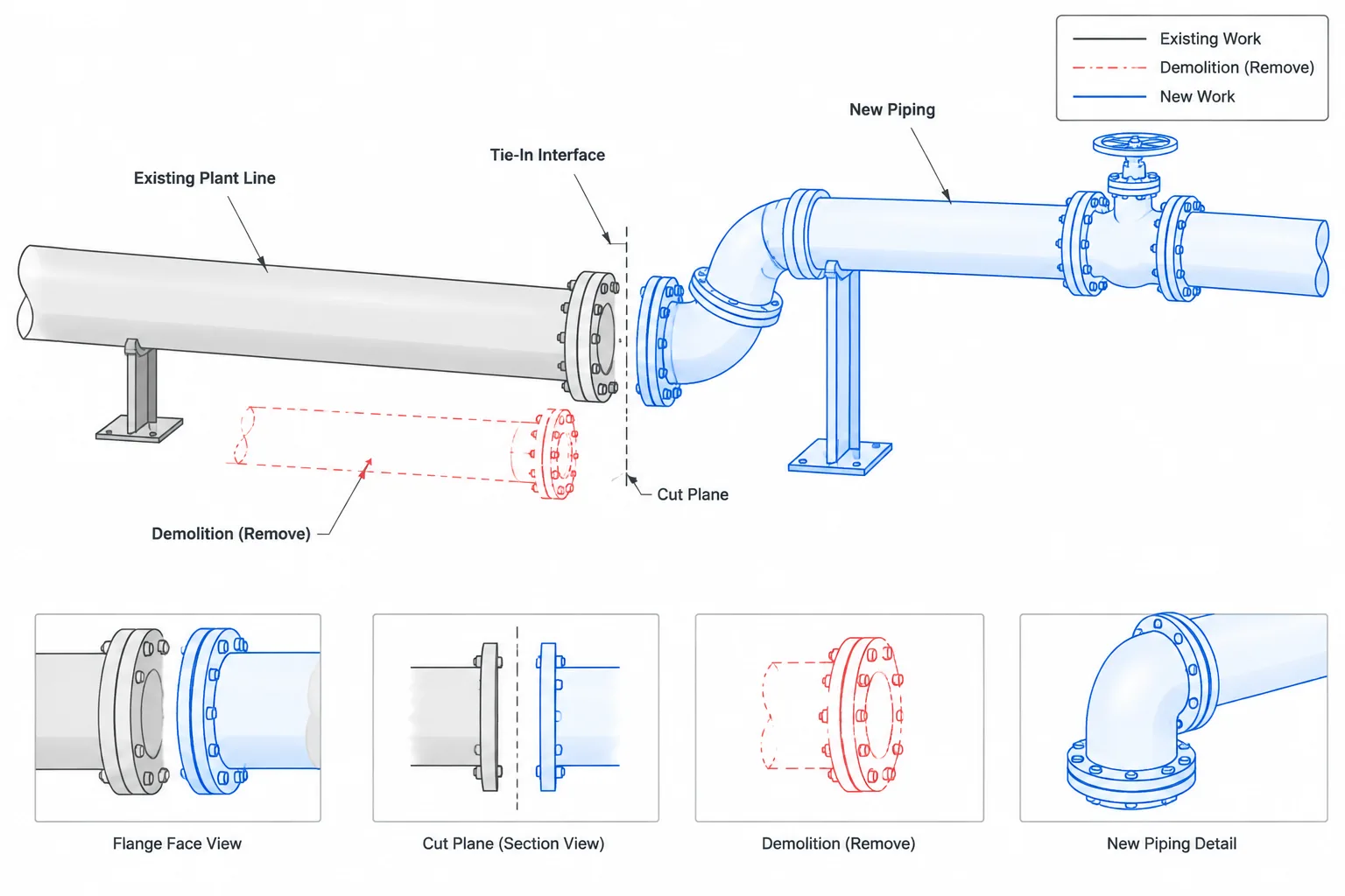
Piping tie-in points in CAD require more control than ordinary routing endpoints because they connect proposed work to field conditions that may be incomplete, outdated, or operationally constrained. A useful tie-in record defines the physical interface, identifies the source and confidence of the existing geometry, and keeps unresolved conditions visible until they are verified.
This guide explains how designers and drafters can coordinate tie-in geometry, demolition limits, field measurements, fabrication decisions, and drawing revisions without presenting assumed existing conditions as verified facts.
A piping tie-in is the controlled interface where new, modified, or temporary piping connects to an existing system. On a drawing, the connection may look like a simple endpoint. In practice, it can involve uncertain field geometry, operating-system constraints, demolition work, isolation planning, material-class changes, and responsibility shared among several disciplines.
Good tie-in documentation does more than identify where a line connects. It establishes what is known, what must be verified, which physical feature controls the location, and where the new design scope begins. This is especially important in brownfield CAD work, where an apparently precise existing model may have been assembled from old drawings rather than current field measurements.
What a piping tie-in point represents
A tie-in point is a defined interface, not merely a coordinate placed on a pipe centerline. Its meaning depends on the connection and the planned work. The controlling point might be a flange face, a pipe cut line, a weld joint, a threaded connection, an equipment nozzle, or a branch location on an existing header.
The tie-in also serves as a boundary between work scopes. It may separate existing piping from new piping, demolition from retained construction, one contractor’s work from another’s, or a vendor package from plant piping. For this reason, the tie-in identifier should remain consistent across the model, drawings, line list, work package, and field records.
Common physical forms
- Flanged connection: The interface is normally related to a specific mating flange face. The documentation must make clear whether an existing flange is retained, replaced, or added.
- Butt-welded connection: The interface may be a planned cut line or weld location on existing pipe. That location should not be confused with the end of the newly fabricated spool.
- Branch connection: The tie-in may require a new branch fitting, fabricated branch, or outlet component on an existing run.
- Threaded, socket-weld, or mechanical connection: The interface must identify the retained component and the assembly condition expected in the field.
- Equipment connection: A nozzle face or other defined equipment interface may function as the tie-in, particularly when existing equipment remains in service.
Separate the tie-in location from the scope boundary
The physical connection and the project scope boundary are often related, but they are not always identical. For example, a project may connect at an existing flange while also replacing several upstream fasteners, a gasket, a short spool, or a valve. Likewise, the model may show demolition extending beyond the location where new fabrication begins.
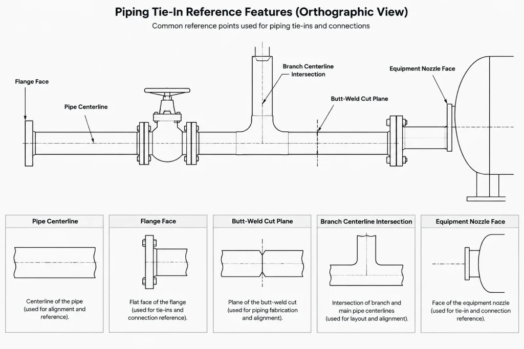
Use separate graphics or attributes when necessary to distinguish:
- The physical connection point
- The limit of demolition
- The limit of new construction
- The retained existing component
- The field weld or assembly joint
- The responsible work package or contractor
If one symbol is expected to communicate all of these ideas, different users may interpret it differently. Explicit labels are usually more dependable than relying on line type or color alone, particularly when drawings are printed in monochrome.
Choose a clear geometric reference
A coordinate is useful only when users understand what feature it locates. Coordinates assigned to piping tie-in points in CAD should identify the referenced object and the project datum. A centerline coordinate does not define an axial cut position by itself, while a flange-face coordinate may not fully define the pipe centerline elevation or orientation.
| Reference feature | What it controls | Potential ambiguity |
|---|---|---|
| Pipe centerline | Lateral position and elevation of the run | Does not necessarily locate the connection along the pipe axis |
| Flange face | Axial mating plane | Requires bore center, orientation, and retained-flange status |
| Pipe cut line | Planned removal and connection plane | Field condition and available straight length must be verified |
| Weld center or joint | Assembly interface | May differ from the fabrication endpoint shown in a spool model |
| Branch centerline intersection | Nominal branch location and orientation | Does not fully describe the selected branch component geometry |
| Equipment nozzle face | Connection to equipment | Must be reconciled with verified vendor or field information |
When the connection plane is angled or the run is skewed, a single plan coordinate may be inadequate. The model and drawing may also need an elevation, direction vector, slope, rotation, or face orientation. The goal is to define the interface without forcing the fabricator or field crew to infer its geometry from a pictorial view.
Treat existing CAD geometry according to its source
Existing piping shown in CAD can have very different levels of reliability. It may come from field survey, point-cloud interpretation, an as-built drawing, an old design model, or a simplified background assembled for routing. These sources should not be treated as equally authoritative.

Assigning a confidence or verification status to each tie-in helps prevent provisional geometry from becoming an undocumented fabrication basis. Useful status descriptions include concept location, drawing-derived location, field-observed location, survey-controlled location, and verified-for-fabrication interface. Project procedures may use different terminology, but the distinction should remain visible.
Do not move existing geometry merely to make the new route connect neatly. If the model contains a mismatch, preserve the discrepancy long enough to determine whether the existing model, the proposed route, or the assumed tie-in condition is wrong. Silent geometric cleanup can hide the exact issue that field verification needs to resolve.
Field verification should answer specific questions
A generic note to verify in field is not a substitute for a verification plan. The design team should identify which facts are uncertain and what measurement or observation will close each uncertainty.
Items commonly checked at a tie-in
- Pipe centerline location, elevation, and direction
- Nominal size, outside diameter, and accessible wall information where relevant
- Connection type and end condition
- Flange type, facing, orientation, and accessible bolt-hole arrangement
- Material identification and piping-class compatibility
- Available straight length for cutting, welding, threading, or coupling installation
- Nearby welds, branches, supports, insulation, linings, and obstructions
- Access for tools, welding, examination, lifting, and component removal
- Whether the line is active, abandoned, drained, or otherwise controlled by operations
- Actual location of the nearest support and the condition created after cutting
Field photographs are helpful, but they should be tied to a location, viewing direction, date, and tie-in identifier. A photograph without context can confirm appearance while failing to establish geometry.
A practical CAD workflow
- Create the tie-in register. Assign a unique identifier and record the related line, service, connection concept, drawing references, verification status, and responsible party.
- Model the best available existing condition. Keep surveyed or verified geometry distinguishable from drawing-derived background information.
- Place the interface at a defined feature. Use a flange face, cut plane, nozzle face, or other explicit reference rather than an arbitrary point near the connection.
- Develop the new route without concealing uncertainty. If the field location is unresolved, use controlled hold geometry or an adjustable spool strategy rather than pretending the endpoint is final.
- Coordinate demolition and retention. Confirm which components remain, which are removed, and whether removal changes support or loading conditions.
- Update the model after verification. Record the source of the change and review connected spools, dimensions, supports, and material takeoffs.
- Freeze the fabrication basis. Before releasing affected work, confirm that the verified interface is reflected in every deliverable that depends on it.
What to show on drawings and isometrics
The drawing should make the tie-in recognizable without requiring the reader to search several unrelated documents. Depending on the project, useful information can include the tie-in number, existing and new line identification, connection type, controlling location, field-weld status, demolition limit, verification note, and continuation reference.
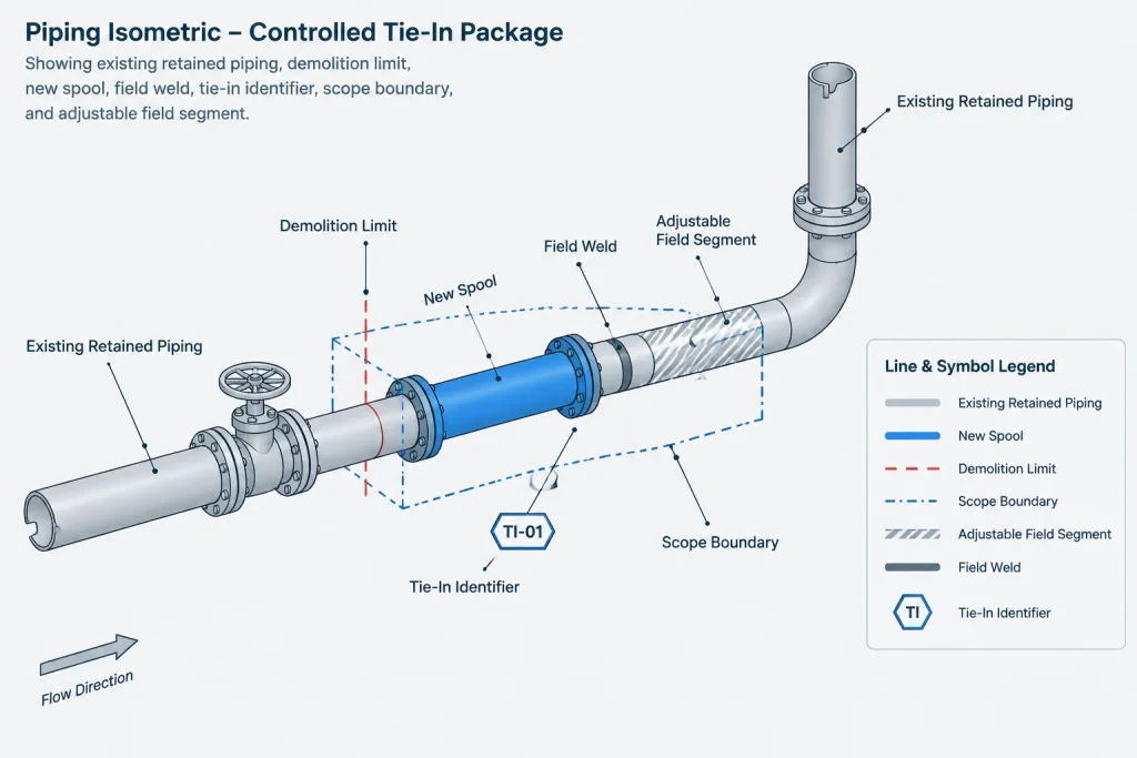
Dimensions should be based on stable references. Avoid dimensioning a tie-in only from another uncertain existing feature. Where the final position must be field adjusted, state which dimension is held and which spool or segment is intended to absorb the adjustment. This prevents multiple parties from independently adding allowance to the same connection.
On isometrics, clearly separate existing retained piping from new fabrication. Show the cut or connection plane and identify components supplied loose for field assembly when applicable. On plans and sections, provide enough surrounding geometry to locate the interface and evaluate access.
Frequent tie-in errors
- Using the visible end of an existing CAD object as the assumed connection plane
- Failing to identify whether an existing flange is retained or removed
- Giving coordinates without defining the referenced feature or datum
- Allowing the model, isometric, and tie-in list to use different identifiers
- Releasing fabrication before field measurements are incorporated
- Ignoring the temporary support condition created when existing pipe is cut
- Treating nominal pipe information as proof of the actual field connection
- Showing a field weld without checking workspace and examination access
- Updating geometry without revising connected dimensions and material records
Final review checklist
Before issuing a piping tie-in package, verify that each interface has one consistent identifier, a defined physical reference, a known coordinate basis, and a documented verification status. Confirm that retained and removed items are unambiguous, the selected connection can be assembled in the available space, and any unresolved field condition is assigned to a responsible party.
A tie-in should be treated as a managed design interface rather than a drafting endpoint. When geometry, scope, field evidence, and document status are controlled together, the CAD model becomes a reliable coordination tool without overstating what is known about the existing plant.
Tie-in control across project deliverables
A tie-in decision can affect more than the piping model. Changes to the connection location or retained components may also affect isometrics, plans, sections, demolition drawings, support information, material records, work packages, and field instructions. Updating only the model can leave conflicting information in documents already used by other disciplines.
A controlled revision should identify what changed, why it changed, which field evidence supports it, and which dependent deliverables require review. This traceability is particularly important when a provisional location becomes an approved fabrication interface.
Coordinate responsibility at the interface
The tie-in register should make responsibility clear rather than relying on informal coordination. The responsible parties may need to confirm geometry, system identity, isolation status, retained components, access, support conditions, and the point at which new construction begins. These responsibilities can belong to different groups, so a completed survey does not automatically mean every tie-in issue has been resolved.
- Piping design: Defines the intended connection and incorporates verified geometry.
- Operations: Confirms system status and operating constraints within the applicable work process.
- Field or survey personnel: Document the requested physical features and the basis of measurement.
- Construction planning: Reviews access, sequence, temporary conditions, and assembly feasibility.
- Document control: Ensures revised interface information reaches affected deliverables and users.
Manage unresolved geometry deliberately
When an interface cannot yet be fully verified, the design should show that uncertainty explicitly. A hold, provisional status, or controlled adjustment location is safer than presenting an assumed endpoint as final. The associated note should identify the information still required and the action that will close the issue.
Once field information is accepted, review the connected route rather than moving only the tie-in marker. The new location may alter spool geometry, clearances, support relationships, demolition limits, component quantities, and field assembly requirements.
Practical quality check before release
Before affected documents are issued, compare the tie-in identifier, physical reference, verification status, retained condition, and scope boundary across each deliverable. Confirm that annotations remain understandable without color and that drawing dimensions refer to stable features. Any open condition should have a named owner and a defined resolution path.
Frequently asked questions
Is a piping tie-in point simply the end of an existing CAD line?
No. The end of a CAD object may reflect drafting convenience, incomplete background geometry, or an old design extent. The actual tie-in must reference a defined physical feature such as a flange face, cut plane, joint, branch location, or equipment interface.
Why should the tie-in location and scope boundary be shown separately?
The connection may occur at one feature while demolition, replacement, or contractor responsibility extends elsewhere. Separate identification prevents the connection plane from being mistaken for the limit of all associated work.
What should be verified before a tie-in is released for fabrication?
Verification should address the geometry, connection condition, retained components, material or piping-class compatibility, available work space, nearby obstructions, support implications, and other project-defined requirements. The accepted information should be incorporated into every affected deliverable.
Can photographs replace tie-in measurements?
Photographs can document appearance, access, and nearby conditions, but they may not establish a reliable connection location or orientation. They are most useful when associated with the tie-in identifier, viewing direction, location context, and the related field record.
How should uncertain existing geometry appear in CAD?
It should remain distinguishable from verified geometry through approved status attributes, notes, layers, symbols, or other project controls. The presentation should not imply fabrication accuracy until the required verification and review are complete.
What happens when a field-verified tie-in moves?
The connected route and dependent documents should be reviewed together. A changed interface can affect dimensions, spool limits, supports, demolition scope, access, material records, and field assembly planning.