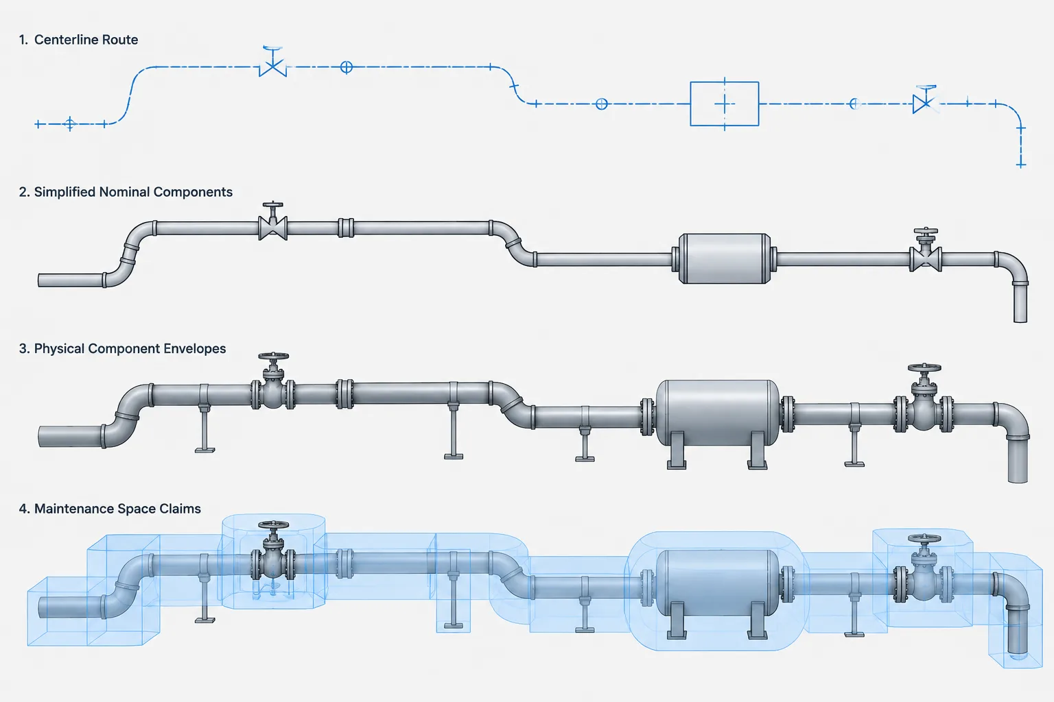
Piping CAD level of detail should be selected according to the decision the model must support. Routing, clash review, procurement coordination, spool development, and maintenance planning do not require the same geometry or the same degree of information certainty.
This guide explains how centerlines, nominal components, space claims, product-specific models, and fabrication geometry serve different purposes. It also highlights why model status, verified connection interfaces, and clearly separated clearance zones are often more valuable than visual realism.
A piping model can represent the same system in several valid ways. A route may begin as a centerline with nominal-size data, develop into a coordinated assembly with fittings and valves, and later include manufacturer-specific geometry or fabrication information. Each representation answers different questions.
The practical issue is not whether a model looks detailed. It is whether its geometry and data are reliable enough for the intended decision. A visually realistic valve may still have an unverified face-to-face dimension, while a simple cylindrical space claim may accurately communicate the clearance required around it. Managing piping CAD level of detail therefore means controlling both geometric complexity and information certainty.
What level of detail means in piping CAD
Level of detail describes how much physical geometry is represented. In piping work, this may range from a routed centerline to a fabrication-oriented assembly showing individual components, joints, and connection locations.
Level of information is related but different. It describes the data attached to or associated with the modeled object, such as:
- Nominal pipe size or DN designation
- Pipe schedule or wall designation
- Material specification and piping class
- Component type and end connection
- Line number, service, and insulation status
- Manufacturer, model, or purchase description
- Verification and revision status
A component can have simple geometry and dependable information, or detailed geometry and uncertain information. Treating these as separate qualities prevents model appearance from being mistaken for engineering authority.
Common representation levels
| Representation | Typical content | Useful for | Important limitation |
|---|---|---|---|
| Centerline route | Pipe path, nominal size, direction, and basic connectivity | Early routing, system studies, and arrangement development | Does not fully describe outside envelopes, fittings, or access |
| Nominal component model | Pipe outside diameter, generic fittings, valves, and flanges | Layout, quantity development, and general coordination | Generic dimensions may not match purchased products |
| Space-claim model | Simplified physical envelope plus operating or service clearance | Clash review, access planning, and interdisciplinary coordination | Envelope geometry may not be suitable for fabrication dimensions |
| Manufacturer-specific model | Verified principal dimensions and connection interfaces | Final equipment interfaces, replacement studies, and procurement coordination | Accuracy depends on approved and current product data |
| Fabrication representation | Joint locations, spool breaks, welds, cut pieces, and controlled dimensions | Shop drawings, spool planning, and installation documentation | Requires project-specific fabrication rules and dimensional control |
These categories are not universal contractual definitions. A project should define its own modeling expectations, deliverables, and acceptance criteria rather than relying on an unexplained level label.
Centerlines are useful engineering geometry
A centerline model is not merely an unfinished model. It can efficiently communicate routing intent, branch relationships, slope direction, connectivity, and approximate run lengths. It is especially useful while equipment locations, structural arrangements, or piping classes are still changing.
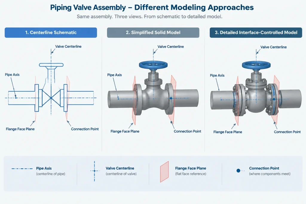
Centerlines become inadequate when a decision depends on physical size. A centerline alone cannot establish whether insulation clears a beam, whether a valve operator can move, or whether flange bolting is accessible. It also cannot show the full sweep of an elbow or the body envelope of an inline component.
Good early-stage practice is to retain the efficiency of centerline routing while identifying where space claims are needed. Large valves, strainers, specialty items, equipment connections, and crowded crossings often need envelopes before the rest of the model needs comparable detail.
Nominal geometry should remain identifiable as nominal
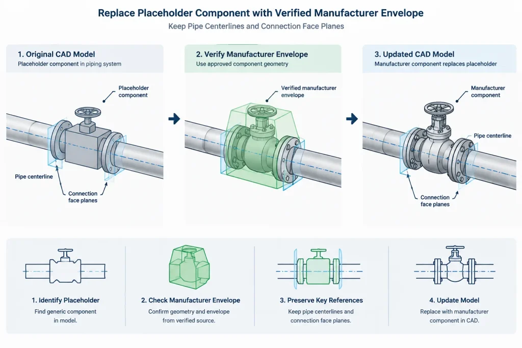
Generic component geometry is appropriate for many layout tasks. Standardized component types can often be represented using controlled reference dimensions, while purchased items may begin as placeholders based on available preliminary data.
The risk arises when a generic shape looks like the final product. A detailed handwheel, actuator, casting, or bonnet can create an impression of accuracy even when its critical dimensions have not been verified. Model metadata, status fields, color conventions, or review reports should distinguish generic geometry from confirmed vendor geometry.
Critical dimensions commonly requiring verification include connection-to-connection length, flange or end details, operator orientation, actuator envelope, drain and vent locations, support points, removal direction, and maintenance access. Which items matter depends on the component and the decisions being made.
Space claims are not the same as component solids
A component solid represents the physical item. A space claim represents an area that should remain available. Combining the two into one undifferentiated object can make clash results difficult to interpret.
Useful space claims may include:
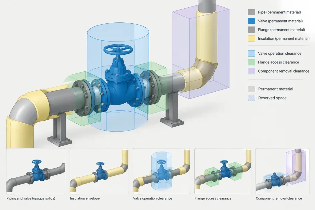
- Valve stem travel and operator movement
- Strainer screen or basket removal paths
- Stud, bolt, or flange access zones
- Insulation and removable insulation covers
- Equipment maintenance and lifting paths
- Areas reserved for field assembly or disconnection
Clearance geometry should be visually and organizationally distinct from permanent material. Reviewers must be able to tell whether a reported interference is a hard physical clash, an insulation conflict, or an intrusion into an access zone.
More detail can make a model less useful
Adding every thread, fastener, casting rib, and small contour does not necessarily improve engineering decisions. Excess detail can increase file size, slow coordination, obscure important interfaces, and make revisions harder to manage. It may also produce distracting clash results against geometry that has no layout significance.
Detail should be driven by a question. If the question is whether a pipeline clears a structure, an accurate outside envelope may be enough. If the question is whether a valve can be removed, the model needs connection breaks and an extraction path. If the question is how a spool will be fabricated, the model needs controlled joint and cut-piece information rather than decorative surface detail.
Connection accuracy often matters more than visual realism
For piping coordination, the most important parts of a component model are frequently its interfaces. These include port centerlines, face planes, end types, orientation axes, and insertion or weld reference points.
A simplified valve body with correct connection planes may be more useful than a realistic body with incorrect overall length. Likewise, a reducer must preserve the intended inlet and outlet sizes, axis relationship, orientation, and end locations. Visual resemblance cannot compensate for a misplaced connection point.
When importing or creating a CAD component, check its origin, units, axis direction, port locations, and reference planes before placing it in a controlled library. A model that inserts correctly only after manual stretching or unexplained offsets is difficult to reuse safely.
Choosing detail by workflow
Routing and arrangement
Use centerlines and nominal components to test connectivity, elevations, slopes, and general access. Add selected envelopes where congestion or equipment interfaces create risk.
Coordination and clash review
Represent outside dimensions, insulation where applicable, operator envelopes, and relevant maintenance zones. Classify clearance objects separately so review teams understand the type of conflict.
Procurement and vendor integration
Replace placeholders only after the controlling product data has been received and checked. Record what was verified and avoid assuming that a downloaded model matches the exact purchased configuration.
Fabrication and spool development
Control weld locations, fitting takeoffs, flange faces, field joints, shop joints, and pipe cut pieces using the project’s fabrication workflow. Do not derive fabrication dimensions from approximate layout solids without confirming their source and status.
Operations and maintenance
Prioritize identification, accessibility, isolation relationships, removable items, and replacement envelopes. Highly detailed exterior geometry may be unnecessary if the operating data and maintenance interfaces are clear.
A practical model review checklist
- What decision is this model expected to support?
- Are the component interfaces verified or provisional?
- Can users distinguish generic, vendor-specific, and field-verified geometry?
- Are physical solids separated from access and maintenance envelopes?
- Does the object contain the correct size, end connection, and specification data?
- Are insulation and lining represented where they affect coordination?
- Could decorative detail be removed without reducing engineering value?
- Are fabrication dimensions based on controlled data rather than visual measurement?
- Will a later product substitution preserve connection points and required clearances?
- Is the model status communicated consistently in drawings and reports?
Model to the required certainty, not the maximum complexity
An effective piping CAD model is detailed enough to answer its intended questions and controlled enough to reveal what remains uncertain. Centerlines, nominal solids, space claims, manufacturer models, and fabrication geometry all have legitimate uses. Problems occur when one representation is used as if it were another.
The best workflow increases detail selectively, verifies critical interfaces, and keeps provisional information visible. This approach supports faster routing, clearer coordination, and more dependable downstream documentation without giving users false confidence in geometry that has not been confirmed.
Turning model detail into a controlled project requirement
Level labels are useful only when the project defines what each representation must contain. A practical modeling plan should describe the required geometry, attached data, verification status, permitted uses, and responsible reviewer for each deliverable. This gives designers and downstream users a common basis for deciding whether an object is suitable for routing, coordination, procurement, or fabrication.
Define acceptance by model purpose
Instead of requesting a generally detailed model, state the question it must answer. A coordination model may need dependable outside envelopes and access zones, while a fabrication model must control connection faces, joint locations, and cut-piece information. These requirements should not be inferred from appearance alone.
Preserve status during model exchange
Geometry can lose context when it is exported, converted, or inserted into another design system. Generic placeholders may become difficult to distinguish from verified product models, and clearance objects may be mistaken for permanent material. Naming rules, object classifications, metadata, and issue documentation should preserve the meaning and status of each object through the exchange process.
Control changes at interfaces
Product substitutions and routing revisions should be reviewed at the connection interfaces before attention shifts to exterior appearance. Port locations, end conditions, orientation, operating envelope, support relationship, and removal direction can affect adjacent piping even when the replacement component appears similar.
Avoid measuring uncontrolled display geometry
Users should not extract fabrication or installation dimensions from a model merely because it can be measured. Before relying on a distance, confirm that the relevant geometry was created from controlled information and approved for that purpose. Approximate layout solids remain approximate even when CAD software reports precise coordinates.
Recommended handoff questions
- Which objects are generic, product-specific, or based on field verification?
- Which connection points and principal dimensions have been checked?
- Are access, insulation, movement, and removal envelopes classified separately?
- What decisions may be made from the model, and what uses are excluded?
- How are substitutions, revisions, and unresolved dimensional assumptions recorded?
- Does exported geometry retain enough information to communicate its status?
A well-managed piping model does not attempt to maximize detail everywhere. It applies verified geometry where decisions depend on it, retains efficient representations where they remain sufficient, and makes uncertainty visible to every user.
Frequently asked questions
Is a centerline model too simple for engineering work?
No. Centerlines are effective for routing intent, connectivity, branch relationships, slope direction, and arrangement development. They become insufficient when a decision depends on physical envelopes, insulation, access, movement, or component interfaces.
What is the difference between a component solid and a space claim?
A component solid represents permanent physical material. A space claim represents an area needed for operation, access, insulation, maintenance, removal, or assembly. Keeping them separate helps reviewers distinguish a hard clash from a clearance conflict.
Does realistic CAD geometry indicate that a component is verified?
No. Visual realism does not establish dimensional authority. Verification depends on the source, configuration, revision status, connection data, and documented review of the geometry.
When should a generic component be replaced with a product-specific model?
Replacement is appropriate when project decisions depend on confirmed product interfaces, envelopes, orientations, or maintenance requirements. The incoming model should be checked against the controlling product information rather than accepted solely because it came from a supplier.
Can coordination geometry be used to create fabrication dimensions?
Only when the geometry and its source have been approved for fabrication use. Nominal solids, preliminary models, and space claims should not be treated as controlled fabrication geometry without verification.
Should every piping component use the same level of detail?
Not necessarily. Detail can be applied selectively according to congestion, interface risk, procurement status, maintenance needs, and the intended deliverable. Consistent status communication is more important than uniform visual complexity.