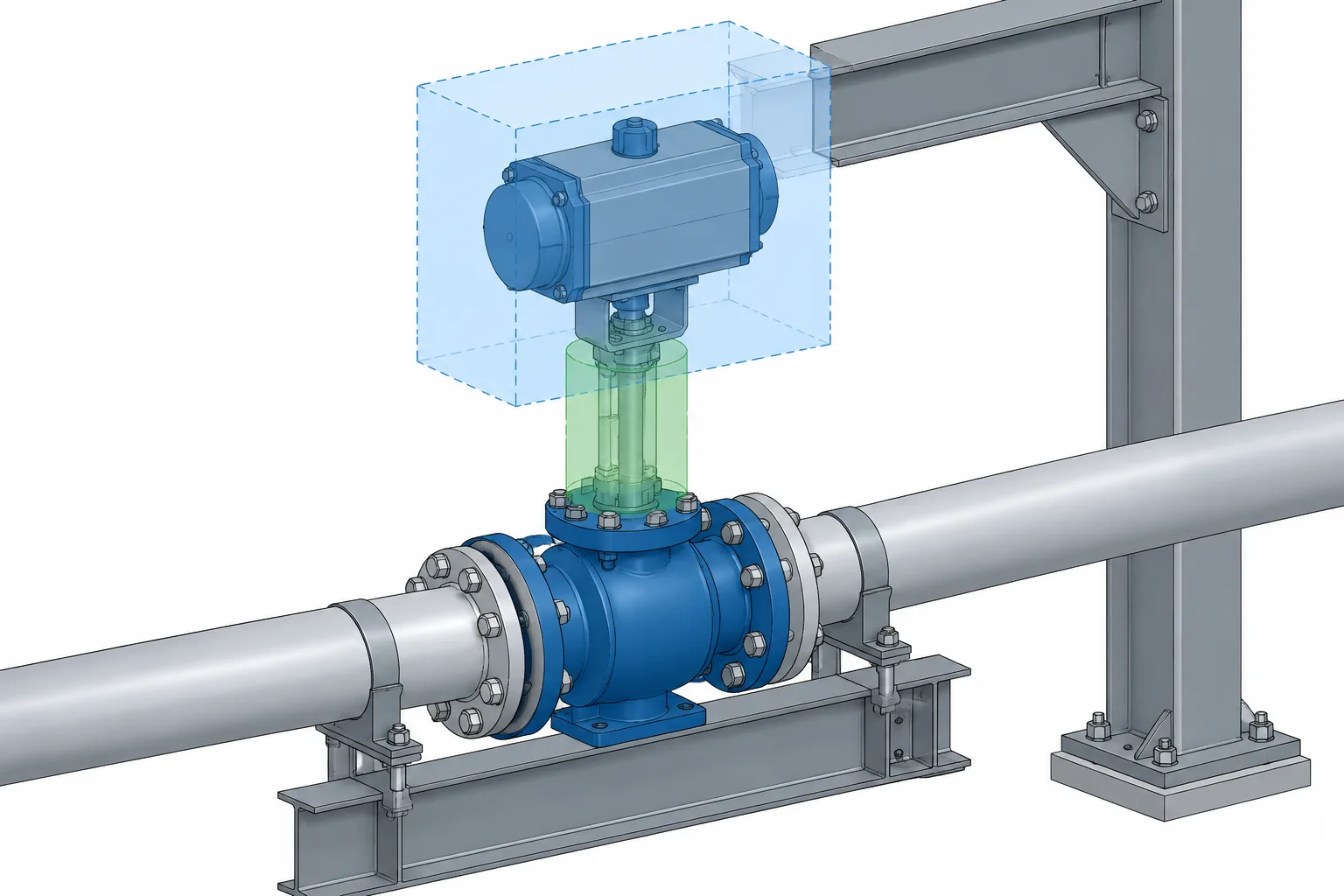
Valve travel envelopes in piping CAD help designers coordinate the space a valve uses beyond its installed body. By representing operator movement, stem extension, removable components, and service paths separately, the model can reveal access problems that an ordinary hard-clash check may overlook.
This guide explains how to classify those spaces, represent them without overloading the model, and communicate whether the geometry is conceptual or based on verified assembly information.
A valve may fit comfortably in a piping model while still being impossible to operate or maintain. The reason is simple: the solid body shown in CAD is only part of the valve’s spatial requirement. Stems rise, handles rotate, actuators move, covers are removed, and internal assemblies may need a clear extraction path.
A valve travel envelope in CAD represents the space needed by those movements. It is different from the permanent physical outline of the installed valve and from the additional clearance needed for tools, personnel, lifting, or component removal. Treating these areas separately makes coordination more useful and prevents an oversized generic clearance box from obscuring the actual problem.
Fixed geometry is not the complete valve envelope
The fixed geometry of a valve usually includes the body, end connections, bonnet, operator housing, and other parts that remain in one location during normal service. This geometry is important for checking interference with nearby pipe, steel, equipment, cable trays, and architectural elements.
However, several portions of a valve assembly may extend beyond that static outline during operation or maintenance. Depending on the valve and operator design, these may include:
- A stem that rises as the valve opens or closes
- A hand lever that sweeps through an arc
- A handwheel or gearbox feature that changes position
- A linear actuator rod or indicator that travels
- A removable bonnet, cover, cap, cartridge, or internal assembly
- Bolts or studs that need axial withdrawal space
- A temporary lifting device or handling path
Not every valve has all of these requirements. A model should therefore be based on the selected valve configuration rather than assumptions associated only with the general valve type.
Three different spaces should be distinguished
Clear coordination depends on separating the installed component from its moving and service-related zones.
| Envelope | What it represents | Typical CAD use |
|---|---|---|
| Static envelope | The physical outline of the valve in its installed condition | Hard-clash checking and arrangement drawings |
| Operating travel envelope | Space occupied by moving parts through their intended motion | Checking stem travel, lever sweep, actuator motion, and indicator movement |
| Maintenance envelope | Space needed to disconnect, remove, lift, or service parts | Maintainability reviews and removal-path coordination |
A personnel access zone may also be required, but it should not automatically be treated as part of the valve’s mechanical travel. Human access depends on the operating task, surrounding platform arrangement, tool use, project criteria, and safety requirements.
Common valve movements that affect layout
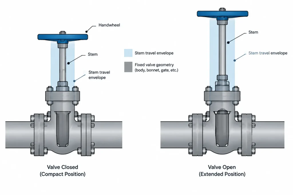
Rising stems
Some valve constructions move the stem outward as the closure element changes position. The required space is therefore greater in one operating state than in another. A model that shows only the closed or compact position can miss an interference above or beside the bonnet.
The designer should verify the direction of stem movement, maximum projected position, and whether any protective tube, indicator, or actuator component moves with it. These details are manufacturer- and configuration-dependent.
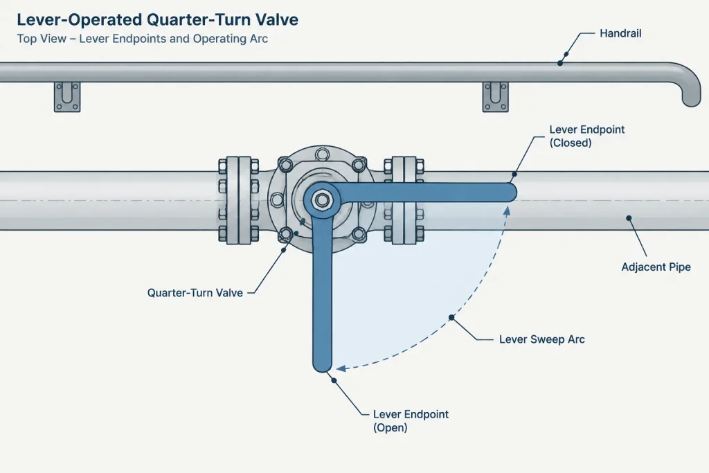
Lever sweep
Quarter-turn valves often use a lever that rotates around the stem axis. Modeling the lever in only one position does not demonstrate that it can complete its intended motion. Nearby handrails, walls, insulation, structural members, and adjacent operators may intersect the sweep even when they do not touch the lever’s normal modeled position.
A swept arc or simplified sector is generally more informative than duplicating the lever in several arbitrary positions. The envelope should reflect the actual lever length and permitted movement after the selected product and installation orientation are known.
Gear operators and handwheels
A gear operator is largely static, but its handwheel must remain reachable and usable. The handwheel itself may not create a large changing envelope, yet surrounding obstructions can prevent a person from gripping and turning it. Where the handwheel is removable or repositionable, the drawing or model should identify which installed orientation is being coordinated.
Pneumatic, hydraulic, and electric actuators
Actuated valves introduce geometry beyond the valve body. An actuator may include a cylinder, spring housing, motor, gearbox, manual override, position indicator, limit-switch enclosure, tubing, conduit entries, and accessory brackets. Some parts move; others require access even though they remain fixed.
A generic cylinder or rectangular box may be acceptable during early routing, but it should be replaced or supplemented with verified interface and envelope data when the actual assembly becomes available. Access to electrical covers, air connections, manual overrides, and local indicators can be just as important as the main actuator outline.
Maintenance clearance is not the same as operating travel
Operating motion is usually repeatable movement that occurs while the valve remains assembled. Maintenance movement involves disassembly or removal. Combining both into one envelope can make reviews confusing because the reviewer cannot tell whether an intrusion prevents operation or merely complicates a future service task.
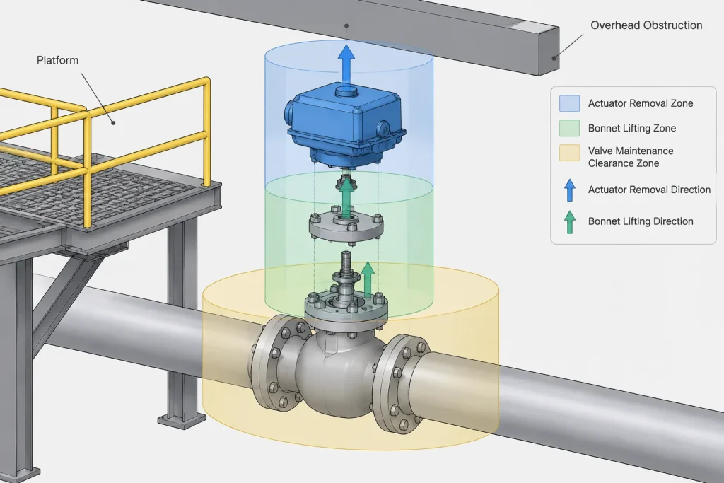
Maintenance space may be needed to:
- Lift a bonnet or top-entry assembly
- Withdraw an internal cartridge or stem assembly
- Remove a side cover or actuator
- Extract flange bolts or other fasteners
- Disconnect tubing, cable, or accessories
- Attach lifting equipment and move the removed part to a landing area
The extraction path matters, not just the final empty volume. A removable assembly may clear the valve body but still be trapped by a beam, platform edge, nearby line, or cable tray. The weight and handling method also influence the required route, although those requirements should come from project and vendor information rather than be inferred from CAD geometry alone.
A practical CAD representation method
The following layered approach keeps the model understandable:
- Model the installed valve geometry. Use the correct end-to-end interfaces, orientation, and operator arrangement for the current design stage.
- Add a distinct travel envelope. Represent the swept or translated volume of moving parts with transparent, lightweight, or non-plot geometry.
- Add maintenance zones separately. Use another layer, object class, or model category for removal and service space.
- Identify the data status. Mark envelopes as preliminary, generic, vendor-based, or field-verified as appropriate.
- Control visibility. Allow travel and maintenance geometry to be turned off for normal drawing production and turned on for coordination.
The envelope should remain associated with the valve so that it moves when the component is relocated or reoriented. A clearance solid left behind at an old coordinate is worse than no envelope because it creates false confidence.
How much detail should be modeled?
The required detail depends on the decision being made. During early layout, a conservative simplified volume may be enough to reserve space. During detailed coordination, the geometry may need to distinguish the body, moving stem, actuator accessories, removable covers, and extraction direction.
Excessive detail can make the model slow and difficult to review. Threads, small fasteners, and internal valve parts usually add little value to a spatial check. A useful envelope communicates the limiting shape, motion, and direction without attempting to reproduce every manufactured feature.
Whenever clearance is critical, generic library geometry should be checked against current manufacturer information. Valve type, size, pressure class, trim arrangement, actuator selection, fail action, accessory package, and mounting orientation can all change the assembly envelope.
Drawing and model communication
Travel envelopes are often coordination aids rather than fabrication geometry. They do not always need to appear on every piping plan or isometric. When shown, use clear linework and notes so that they cannot be mistaken for physical material.
Useful documentation may include:
- A dashed outline for the fully extended stem position
- An arc showing lever rotation
- An arrow indicating bonnet or actuator removal direction
- A labeled maintenance zone on an arrangement drawing
- A model property identifying the source and status of envelope data
- A review note where final clearance depends on vendor information
Do not dimension a preliminary envelope as though it were an approved product requirement. If a critical layout dimension comes from a selected valve assembly, retain its source and revision status in the project’s document-control workflow.
Review questions for valve clearance
A focused model review should ask more than whether the valve body clashes:
- Can the valve reach every required operating position?
- Does a rising stem or actuator rod intersect nearby construction?
- Can the operator be reached from the intended floor or platform?
- Can removable covers and fasteners be withdrawn?
- Is there a continuous path for removing major service parts?
- Will insulation, tracing, cladding, or fire protection reduce the available space?
- Are conduit and tubing routed with enough flexibility for access?
- Is the envelope based on generic assumptions or verified assembly data?
Why envelope status matters
Valve travel and maintenance space often become more accurate as procurement progresses. Early design may use a generic operator, while later design uses a selected actuator and accessory arrangement. The model should make that progression visible.
A practical status field can distinguish conceptual geometry from supplier information and field verification. This helps reviewers understand what has actually been coordinated and what remains an open interface. It also supports replacement planning: a future valve may match the piping connections while having a different stem projection, actuator outline, or service requirement.
The key principle is to model space according to purpose. Static geometry answers where the valve is. A travel envelope answers where its parts move. A maintenance envelope answers what space must remain available for service. Keeping those questions separate produces clearer CAD reviews and more maintainable piping layouts.
Using valve envelopes in a coordination workflow
An envelope becomes most useful when the project team can identify what kind of conflict it reports. Contact with the installed valve is a physical clash. Intrusion into an operating envelope may prevent normal movement. Intrusion into a maintenance zone may restrict future disassembly or removal. These conditions should not be assigned the same review priority automatically.
Where the CAD system permits, assign each envelope a clear category, visibility rule, and data-status property. The associated record can identify the valve tag, represented movement, geometry source, and verification status without embedding excessive detail in the model.
Coordinate orientation changes carefully
Rotating a valve or operator can resolve one conflict while creating another. A revised orientation may improve access to a handwheel but redirect stem travel, cover removal, conduit access, or actuator withdrawal toward surrounding construction. Recheck every associated envelope whenever the valve, operator, platform, or nearby piping changes.
Keep assumptions visible
Generic envelope geometry is useful for reserving space, but it should remain visibly different from verified supplier geometry. If the selected assembly is not yet known, describe the modeled condition as an allowance rather than presenting it as a final equipment requirement. Critical clearances should be reviewed again when current valve and actuator information becomes available.
Recommended review ownership
Valve clearance is not solely a piping-model issue. Piping designers typically control placement and orientation, while other disciplines may affect structural access, electrical connections, instrument tubing, platforms, insulation, lifting arrangements, and removable routes. A coordinated review should identify who confirms each interface and how unresolved assumptions are tracked.
The final model should communicate both occupied space and reserved space. That distinction helps construction, operations, and maintenance reviewers understand whether an apparent intrusion is a physical clash, an operating restriction, or a serviceability concern requiring further evaluation.
Frequently asked questions
Is a valve travel envelope part of the physical valve model?
No. It is coordination geometry representing space occupied during movement. It should be distinguishable from the installed valve and should not be interpreted as fabricated material.
Should operating and maintenance envelopes be combined?
They are generally clearer when represented separately. Operating travel covers repeatable movement while the valve remains assembled, whereas maintenance clearance covers disconnection, withdrawal, lifting, or removal activities.
Can a generic valve CAD block provide a reliable travel envelope?
It can support preliminary layout if its assumptions are documented. Final coordination should use current information for the selected valve, operator, accessories, and mounting orientation whenever that information is available.
Should personnel access be included in the mechanical envelope?
Not automatically. Personnel access depends on the task, platform arrangement, tools, surrounding obstructions, and project safety criteria. It can be modeled as a separate access zone so reviewers understand its purpose.
What happens when a valve is reoriented in the model?
Its travel, maintenance, and access geometry should be reoriented and reviewed with it. Associative geometry or grouped model objects can reduce the risk of leaving an outdated clearance zone at the former location.
Do valve envelopes belong on piping drawings?
They may be shown where they communicate a relevant coordination or maintenance requirement, but they do not need to appear on every drawing. When displayed, linework and notes should make clear that the envelope represents reserved space rather than physical material.