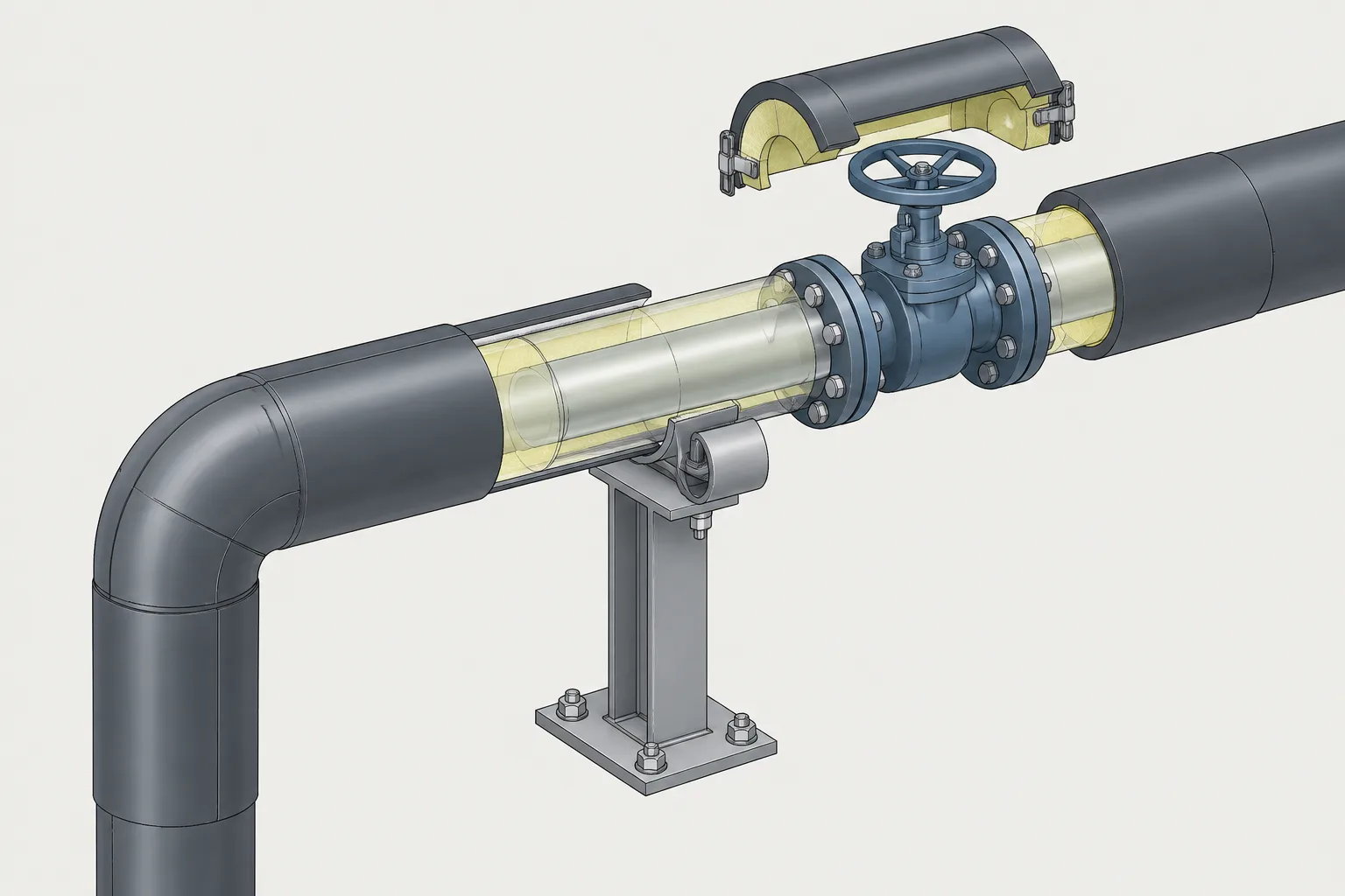
Piping insulation in CAD should communicate the finished physical envelope without confusing installed materials with required working space. A useful model distinguishes the bare component, insulation, protective jacketing, removable covers, and access zones so each can be reviewed for the correct purpose.
This distinction matters during routing, clash detection, support coordination, drawing production, and maintenance planning. The following guidance explains how to represent insulation-related geometry while keeping thickness and system selections tied to approved project information.
Pipe insulation changes the physical envelope of a piping system even though it does not change the pipe’s nominal size. A bare pipe model may be sufficient for some routing tasks, but it can conceal conflicts with structures, adjacent lines, supports, valve operators, instruments, and maintenance access. Effective piping insulation in CAD therefore requires more than applying a visual texture or assigning an insulation field in a line list.
The designer must distinguish among the pipe itself, the insulation system, its protective covering, and any additional space needed to install or remove that system. These layers may be controlled by different documents and may require different levels of geometric detail.
Pipe geometry and insulation geometry are different
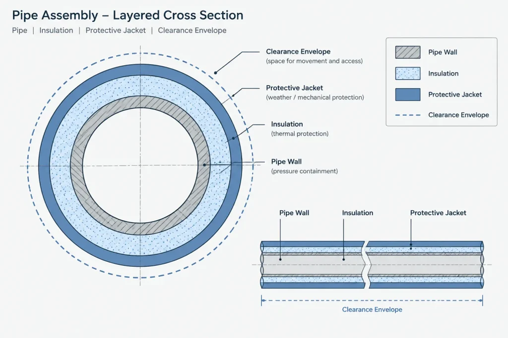
The outside diameter of the pipe or fitting defines the starting surface for most insulation geometry. Insulation thickness then extends outward from that surface. A jacket, cladding, coating, vapor barrier, or weatherproof covering may add another layer, depending on the service and insulation system.
This creates several related but distinct envelopes:
- Bare component envelope: The physical pipe, fitting, flange, valve, or other component before insulation is considered.
- Insulated envelope: The expected outside surface of the installed insulation system.
- Finished jacket envelope: The exterior surface after protective covering or cladding is included.
- Installation and maintenance envelope: Space needed to fit, close, remove, or replace insulation and removable covers.
These envelopes should not be treated as interchangeable. A clash check against the pipe outside diameter alone does not prove that the insulated line will fit.
Where insulation thickness data should come from
Insulation thickness is normally a project-controlled value. It may depend on service temperature, process objectives, personnel protection, condensation control, energy conservation, acoustic requirements, fire protection, material selection, or project practices. The applicable insulation specification or project data should govern.
A CAD catalog should not silently assign insulation based only on nominal pipe size. Two lines with the same pipe size and material may require different insulation systems. Conversely, some components on an insulated line may be left bare, fitted with removable covers, or treated differently from adjacent straight pipe.
Useful model properties can include:
- Insulation specification or system identifier
- Nominal insulation thickness
- Insulation purpose or service category
- Jacket or protective covering type
- Heat-tracing status
- Extent or termination status
- Removable-cover requirement
- Source document and revision
The model property and visible geometry should agree. If a line is tagged as insulated but no insulation envelope is displayed or included in interference checks, users need to understand that limitation.
Why a simple offset cylinder is not always enough
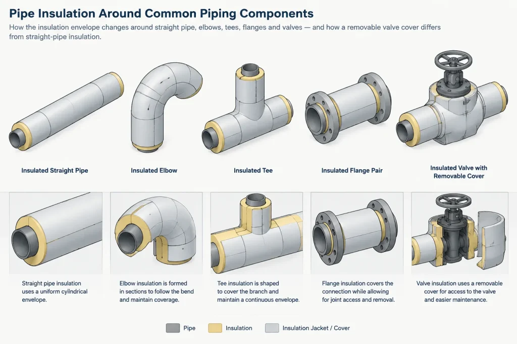
On straight pipe, insulation can often be represented as a concentric cylindrical envelope. Real piping assemblies are more complicated. Fittings, valves, flanges, strainers, specialty items, and instruments create local changes in shape.
Fittings
Elbows and tees generally require insulation to follow their changing geometry. A crude cylinder around the centerline may understate the envelope near fitting bodies or branch intersections. The required model detail should match the coordination purpose rather than trying to reproduce every insulation seam.
Flanges and bolted joints
A flange pair is wider than the connected pipe and includes bolts, nuts, and a joint interface. Insulation around a flange may use a shaped cover or removable arrangement. The model should preserve access requirements when the joint must be opened. Extending the straight-pipe insulation cylinder through the joint can hide both the actual envelope and the maintenance issue.
Valves and inline equipment
Valve bodies may be insulated while stems, operators, vents, drains, nameplates, or selected bonnet areas remain accessible. Some valves require removable covers instead of permanent insulation. The correct treatment depends on the project insulation details and equipment requirements.
Small branches and instruments
Insulation can crowd root valves, impulse connections, tubing, drains, and instrument access points. A branch that clears the bare pipe may become inaccessible after insulation is installed. Model reviews should consider both the main-line insulation and the usable space around the connection.
Insulation envelope versus clearance envelope
An insulation envelope represents installed material. A clearance envelope represents space that should remain available. Combining them into one anonymous CAD solid makes it difficult to determine whether a clash is physical, operational, or maintenance-related.
| CAD object | What it represents | Typical review use |
|---|---|---|
| Bare piping geometry | Pipe and component bodies | Routing, fabrication geometry, and connection control |
| Insulation geometry | Installed thermal or protective insulation | Physical interference and spacing review |
| Jacket envelope | Finished exterior covering where separately modeled | Final outside envelope and weatherproofing coordination |
| Removable-cover envelope | Cover around a valve, flange, or specialty item | Removal path and access planning |
| Work clearance zone | Reserved space rather than installed material | Installation, inspection, operation, and maintenance review |
Distinct object types, layers, display classes, or model categories allow reviewers to isolate these conditions. They also reduce false clashes when a clearance zone intentionally overlaps a component it serves.
Heat tracing and insulation coordination
Heat tracing may occupy space between the pipe surface and insulation, and it may introduce junction boxes, connection kits, sensors, leads, or other local items. The tracing itself does not necessarily need full physical detail throughout the model, but its presence should be documented where it affects insulation selection, support details, electrical coordination, or access.
A practical CAD approach is to store tracing as controlled line data while modeling significant local hardware where coordination is necessary. Designers should avoid assuming that adding insulation automatically accounts for tracing hardware.
Supports can interrupt the insulation system
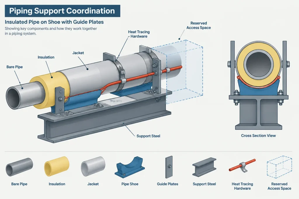
Pipe supports require special attention because the load path and insulation system interact. Shoes, saddles, clamps, guides, and anchors may pass through, surround, or sit outside the insulation envelope. Some services use load-bearing insulation or other project-specific support details. The CAD model should follow the approved support and insulation details rather than improvising a generic arrangement.
Common coordination questions include:
- Does the support act on the pipe, a shoe, or the outside of the insulation system?
- Is insulation continuous at the support location?
- Does a clamp need space beyond the insulation envelope?
- Will the jacket interfere with guide plates or stops?
- Is weather sealing or local inspection access required?
Support designers and piping designers should use the same reference envelope. Otherwise, one discipline may dimension from bare pipe while another assumes the finished insulated surface.
Modeling approaches for different project stages
Not every project needs detailed insulation solids from the beginning. The representation can develop with the design:
- Early routing: Use a conservative envelope or display style for lines known to require insulation.
- Coordination model: Apply verified thickness data and include major component covers, support interfaces, and tracing hardware where relevant.
- Detailed design: Resolve terminations, removable sections, penetrations, valve access, and specialty details.
- Deliverables: Show only the information needed for the drawing purpose while retaining controlled properties in the model or project database.
If insulation data remains unverified, it should be identified as provisional rather than presented as a finished design value. A temporary model envelope can support routing, but it should not be mistaken for approved construction information.
Insulation terminations and boundaries
Insulation does not always continue without interruption from one end of a line to the other. It may stop at equipment, transition between systems, exclude selected components, or require special treatment at penetrations and outdoor boundaries.
These changes should be locatable in the model and drawings. A database property that applies to an entire line may be insufficient when only part of the line is insulated or when component treatment varies. Segment-level data, insulation break markers, notes, or dedicated details can communicate the boundary more clearly.
Practical review checklist
- Confirm insulation data against the current project specification or approved line data.
- Check that the model uses pipe and fitting outside geometry as the correct basis.
- Include insulated envelopes in coordination reviews, not only bare piping.
- Review flanges, valves, strainers, instruments, and specialty items individually.
- Separate installed insulation from maintenance and installation clearance zones.
- Coordinate heat-tracing hardware with insulation and nearby structures.
- Verify support interfaces using the applicable project details.
- Identify insulation starts, stops, exclusions, and system transitions.
- Preserve access to operators, labels, vents, drains, and bolted joints as required.
- Mark unverified thicknesses or cover geometry as provisional.
Use insulation geometry as controlled design data
Piping insulation in CAD is most useful when it is treated as controlled engineering information rather than decoration. Its geometry affects routing space, support arrangements, component access, penetrations, clash results, and maintenance planning. At the same time, the model should not imply more certainty than the project data supports.
A sound workflow keeps bare piping, installed insulation, protective covering, and clearance zones conceptually separate. It also connects each modeled envelope to an identifiable specification or project decision. That approach gives designers a realistic finished envelope while preserving the distinction between physical components, insulation systems, and reserved working space.
Model governance and quality control
Insulation geometry remains reliable only when its source, status, and scope are clear. Model properties should identify whether the information is approved, provisional, excluded, or awaiting confirmation. This prevents a visually complete envelope from being mistaken for finalized engineering data.
Check geometry against assigned data
A quality review should compare visible insulation with the properties assigned to the line or component. Reviewers should investigate lines that carry insulation data but show no envelope, as well as modeled envelopes that have no documented system assignment.
Control local exceptions
Line-level data may establish the general requirement, but component-level exceptions still need to be recorded. Valves, flange joints, instruments, supports, penetrations, and insulation boundaries can require treatment that differs from the adjoining pipe. These exceptions should remain visible to both model users and drawing producers.
Use display controls intentionally
Separate display categories make it possible to review bare piping, insulation, jacketing, removable covers, and clearance zones independently. Clear visual conventions also help teams distinguish a physical clash from an intrusion into reserved maintenance space.
Information to preserve during model exchange
When models move between authoring, coordination, and review systems, insulation should not become an unexplained generic solid. The exchange workflow should preserve the relationship between the envelope and the component it serves, along with the status and purpose of the modeled geometry.
- Keep insulation associated with the correct pipe segment or component.
- Retain identifiers used to trace the envelope to controlled project data.
- Confirm that exported geometry participates in the intended clash tests.
- Prevent clearance zones from being interpreted as fabricated or installed objects.
- Review local covers and insulation boundaries after translation or model federation.
The final check is practical: a reviewer should be able to determine what will physically exist, what can be removed, and what space must remain available without relying on color alone.
Frequently asked questions
Does insulation change the nominal pipe size?
No. Insulation changes the outside envelope used for coordination, but it does not redefine the nominal size of the pipe.
Should jacketing be modeled separately from insulation?
Separate modeling is useful when the finished covering affects coordination or must be identified independently. If it is represented within a combined envelope, the modeling convention should be documented so reviewers understand what the outer surface includes.
Is an insulation envelope the same as maintenance clearance?
No. The insulation envelope represents installed material. Maintenance clearance represents space that should remain available for access, removal, inspection, or replacement.
How should removable insulation covers be represented?
Represent the installed cover and, when coordination requires it, a distinct access or removal zone. The geometry should follow approved project details rather than a generic assumption.
Can insulation thickness be assigned from nominal pipe size alone?
Not reliably. Thickness and system selection are controlled by project requirements and service conditions. Nominal size may be part of the applicable criteria, but it is not sufficient by itself.
What should happen when insulation information is not yet approved?
Any temporary envelope should be labeled as provisional and traceable to its planning basis. It can support routing decisions, but it should not appear to be approved construction information.