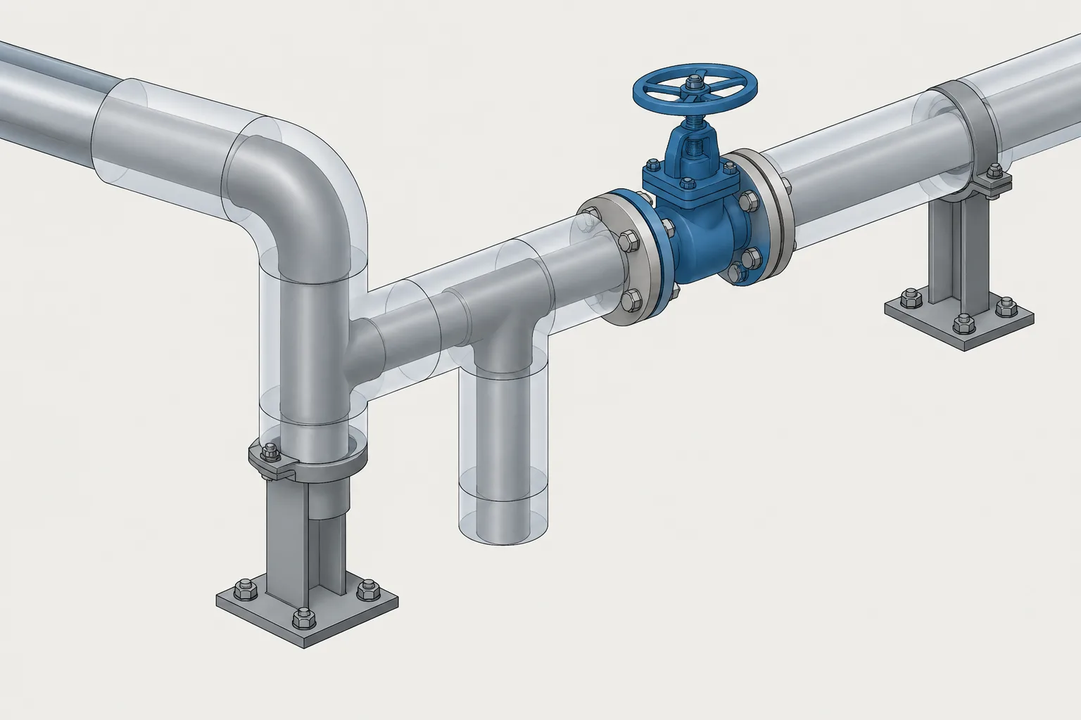
Pipe insulation in CAD should be treated as controlled coordination geometry rather than a decorative offset around the piping. The model must distinguish the bare piping, the installed insulation assembly, and any additional space required to operate equipment or remove covers.
This guide explains how to select an appropriate representation, manage insulation changes, coordinate component and support interfaces, and document assumptions without making the CAD model the source of unverified insulation requirements.
Pipe insulation is easy to treat as a drafting overlay, but its outer surface often controls the space a piping system actually occupies. Supports, adjacent lines, structural steel, equipment access, valve operation, and removable covers may all be affected by an insulation envelope that is larger than the bare pipe.
Representing pipe insulation in CAD does not require modeling every layer in full detail. It does require a consistent method for carrying verified insulation data, displaying the relevant envelope, and identifying locations where the insulation system changes. The appropriate level of detail depends on whether the model is being used for early routing, coordination, fabrication, or installation planning.
Pipe Outside Diameter Is Not the Insulated Envelope
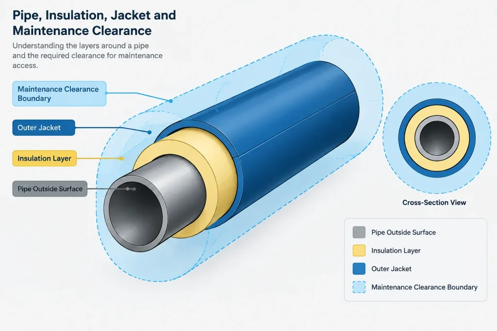
The pipe outside diameter describes the exterior of the pipe wall. The insulated envelope extends beyond that surface and may include insulation material, jacketing, vapor barriers, protective covers, or other specified layers. A piping centerline can therefore be geometrically correct while the complete insulated assembly clashes with nearby objects.
CAD users should keep three different boundaries conceptually separate:
- Pipe geometry: the physical pipe, fittings, flanges, and components.
- Insulation envelope: the nominal outside boundary of the installed insulation system.
- Working or removal clearance: additional space needed to install, inspect, operate, or remove an item.
The insulation envelope is not automatically a maintenance clearance. A removable valve cover may fit within a modeled envelope but still require extra room for release straps, panel separation, or lifting.
Where Insulation Data Should Come From
Insulation thickness and construction should come from controlled project information rather than visual assumptions. Depending on the project, the governing source may be an insulation specification, line list, piping material class, equipment data, service schedule, or approved vendor document.
The CAD model should not silently become the authority for insulation selection. When data are missing or conflicting, use an identified placeholder only if the project workflow permits it, record the unresolved item, and replace it after technical confirmation. Do not infer insulation thickness merely from pipe size, service name, or the appearance of another line.
Useful insulation properties to track
- Insulated or uninsulated status
- Insulation specification or service code
- Verified thickness
- Jacketing or protective-system designation when relevant
- Heat-tracing status and tracing reference
- Personnel-protection limits, if separately defined
- Removable-cover requirements
- Start, stop, and transition locations
- Data source and revision status
Not every property must appear graphically on every drawing. Structured model data can carry information that would otherwise make plans and isometrics difficult to read.
Choosing the Right CAD Representation
The most useful representation is the least detailed one that supports the design decision being made. Excessive geometry can slow coordination without improving accuracy.
| Representation | Typical use | Main limitation |
|---|---|---|
| Centerline with insulation attribute | Early routing and data management | Does not visibly expose envelope clashes |
| Expanded cylindrical envelope | General spatial coordination | May simplify fittings and component covers |
| Two-line or hidden-line outline | Plans, elevations, and selected details | Can become visually crowded |
| Component-specific insulation geometry | Congested areas and maintenance studies | Requires verified construction information |
| Separate clearance volume | Removal and access review | Must not be confused with installed material |
A practical model may combine these methods. Straight pipe can use a simple expanded envelope, while valves, strainers, instruments, and flanged joints receive more specific geometry only where access or coordination demands it.
Thickness Changes and Insulation Breaks
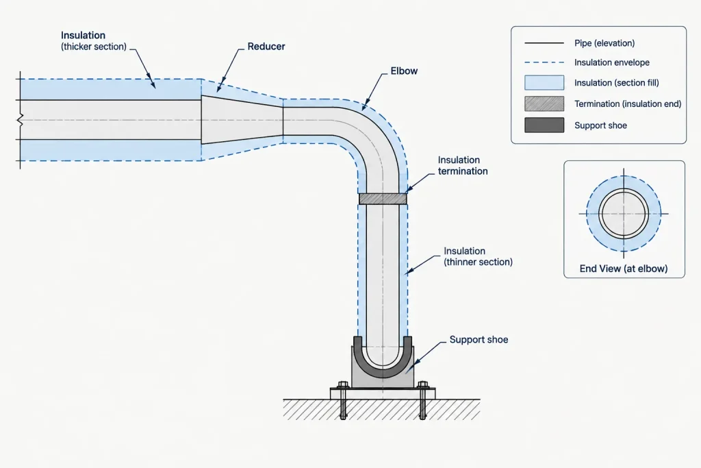
Insulation does not always continue unchanged along an entire line. Thickness may change because of service conditions, personnel protection, environmental exposure, tracing requirements, or a transition between project specifications. Insulation may also terminate near equipment, specialty items, field connections, or components that require a different treatment.
Each transition should have a defined location. Avoid showing a vague graphical change with no dimension, component reference, coordinate, or other reproducible control. A transition can be tied to a weld, flange face, support reference, equipment nozzle, or established coordinate, depending on project practice.
Review insulation changes independently from piping specification breaks. They may occur at the same location, but they represent different design controls. A change in pipe material does not automatically prove that insulation changes, and an insulation transition does not necessarily change the pressure-containing piping specification.
Fittings, Flanges, and Valves
A uniform offset around the pipe centerline is often adequate for preliminary coordination, but real insulation systems around components are rarely perfect cylinders. Elbows may have segmented covers, reducers create tapered envelopes, and tees enlarge the occupied region around the branch intersection.
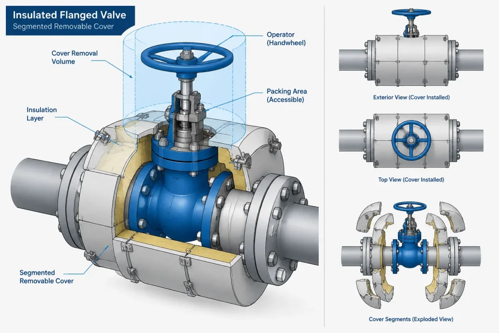
Flanged joints require particular care. The insulated outside shape may need to accommodate the flange rims, bolting, and a removable or reusable cover. If a joint must be opened during maintenance, surrounding space should be checked for both bolt access and cover removal. Modeling only the straight-pipe insulation diameter can conceal these conflicts.
Valve insulation depends on the valve type, bonnet arrangement, operator, operating temperature, and project requirements. The body may be insulated while the stem, packing area, operator, or other features remain accessible. A generic solid enclosure around the entire valve can incorrectly imply that operable or serviceable parts are buried.
Supports and Insulation Interfaces
Pipe supports are frequent insulation-interface points. The design may use shoes, saddles, load-bearing insulation, vapor stops, shields, inserts, or other project-specific arrangements. These details affect both geometry and load transfer.
CAD documentation should distinguish between a support attached to the pipe and an item fitted outside the insulation. Do not simply pass an insulation cylinder through every support without checking the applicable support detail. Conversely, do not create an arbitrary gap because it looks convenient in the model.
At support locations, verify:
- Whether insulation continues through the support zone
- Whether a shoe or other attachment changes the outer envelope
- Whether jacketing must terminate or be sealed
- Whether movement can occur without damaging the insulation system
- Whether the support detail and piping model use the same orientation
Heat Tracing Is Related but Not Identical
Heat tracing and insulation are coordinated systems, but they should remain separate data concepts. A traced line generally relies on insulation to retain heat, yet the tracing circuit, power or supply connection, monitoring point, and installation requirements have their own documentation.
For general arrangement modeling, it may be sufficient to identify the line as traced and show the resulting insulation envelope. Detailed tracing paths are normally added only when needed for installation or interface coordination. If tracing hardware creates a local projection, junction location, or access need, that feature should be represented or clearly referenced.
Removable Covers and Maintenance Space
Removable insulation commonly occurs around valves, strainers, flanged equipment connections, and components requiring inspection. The installed cover geometry is only one part of the review. Designers must also consider how the cover separates and where it can be moved after removal.
A useful CAD approach is to model the installed cover as normal geometry and place removal space on a separate, non-plotting or selectively displayed layer. This makes it clear that the additional volume is a coordination aid rather than permanent material.
Questions to ask include:
- Can fasteners or closures be reached?
- Can cover sections be separated without hitting steel or another pipe?
- Does the valve operator remain usable?
- Can flange bolts, strainers, or internal parts be withdrawn?
- Is there a safe path for handling the removed cover?
Drawing and Model QA Checklist
- Confirm insulated status against current controlled data.
- Verify that insulation thickness is not being inferred from graphics.
- Check straight runs, elbows, branches, reducers, and component bodies.
- Locate insulation starts, stops, and thickness transitions reproducibly.
- Review flange and valve envelopes rather than relying only on pipe offsets.
- Coordinate insulation with supports, shoes, guides, and structural penetrations.
- Keep insulation envelopes distinct from maintenance-clearance volumes.
- Check traced-line attributes against the applicable tracing documents.
- Review congested areas with insulation displayed, not only bare-pipe geometry.
- Record assumptions and unresolved insulation data before model issue.
A Model Envelope Is a Coordination Tool
Pipe insulation in CAD should communicate occupied space and design intent without pretending to define unverified construction details. A simplified envelope is valuable when its basis is known, its transitions are controlled, and its limitations are understood.
The most reliable workflow begins with verified project data, uses consistent model properties, and adds detailed geometry only where it improves coordination. This approach helps prevent insulation clashes while keeping the piping model readable, maintainable, and suitable for its intended design stage.
Applying the Method in a Project Workflow
Before adding insulation geometry, determine which controlled project document owns the insulation requirement and which model property identifies that source. This allows reviewers to trace the displayed envelope back to current design information rather than relying on its appearance.
Separate data, geometry, and clearance
A reliable workflow treats these as related but distinct model elements:
- Insulation data records status, specification references, verified thickness, tracing relationships, transitions, and revision information.
- Envelope geometry shows the space occupied by the installed insulation system at the detail level needed for coordination.
- Access geometry reserves temporary space for operation, inspection, disassembly, or cover removal.
Keeping these elements separate makes display control easier and reduces the risk that a maintenance volume will be interpreted as permanent construction.
Control changes at identifiable locations
Every insulation start, stop, or change should be tied to a reproducible model reference. The selected reference must remain understandable when the model is reviewed, revised, or exchanged with another discipline. If the location is unresolved, flag it as an open design item rather than placing an apparently final transition.
Use targeted detail in congested areas
Simple envelopes are generally easier to manage along unobstructed runs. More specific geometry becomes useful where flanges, valve bodies, operators, branches, supports, tracing hardware, or removable covers affect occupied space. Detail should answer a coordination question; it should not imply construction information that has not been verified.
Check what downstream drawings communicate
Model properties do not automatically appear clearly in plans, elevations, sections, or isometrics. Confirm that insulation status and transition information are communicated through the project’s approved annotation, symbology, schedules, or references. Graphic outlines should supplement controlled data rather than replace it.
Review Priorities Before Model Issue
A final review should compare the insulation envelope with adjacent piping, structural members, penetrations, supports, equipment access, and component operation. Reviewers should also verify that hidden or simplified insulation geometry has not allowed a clash to pass unnoticed.
Any placeholder, missing source, or unresolved interface should remain visible in the project’s issue-management process. A clean-looking envelope is not evidence that the insulation design has been confirmed.
Frequently Asked Questions
Can the insulated envelope be calculated from the pipe outside diameter?
The pipe outside diameter is only the starting boundary. The complete envelope depends on verified insulation thickness and any specified jacketing, barriers, covers, or local component treatment. CAD users should obtain those requirements from controlled project information.
Should insulation be modeled as part of the pipe object?
It may be associated with the pipe through properties, but separate display control is usually valuable. The project’s CAD system and data workflow should determine whether the envelope is generated, attached, or managed as separate geometry.
Is the insulation envelope the same as pipe spacing clearance?
No. The envelope represents the installed assembly. Spacing decisions may also need to consider construction tolerance, access, operation, inspection, disassembly, and removal paths.
How should a removable insulation cover be represented?
Show the installed cover using verified geometry appropriate to the coordination need. Represent opening, separation, lifting, or withdrawal space independently so reviewers can distinguish temporary access space from permanent material.
How should insulation changes appear in CAD?
Record the change in structured data and locate it against an identifiable model reference. Add graphical annotation or transition geometry where required by the drawing or coordination workflow.
Does a piping specification break also define an insulation break?
Not automatically. Piping specifications and insulation requirements govern different parts of the design. Their transitions may coincide, but each change should be confirmed from its own controlled source.
Should every fitting have detailed insulation geometry?
Not necessarily. Use the simplest representation that supports the current design decision. Add component-specific geometry where shape, access, support interfaces, or removable construction materially affects coordination.
Who should resolve conflicting insulation information?
The conflict should be referred through the project’s technical and document-control process to the responsible discipline. CAD personnel should record the discrepancy and avoid silently selecting a value from appearance or precedent.