A pipe’s nominal size, material, and wall designation do not fully describe the item needed for fabrication or purchasing. The condition at each end also matters. A straight pipe segment may be supplied with plain ends, prepared bevels, threads, grooves, or different conditions at opposite ends.
Pipe end types affect how components connect, where dimensions terminate, what fabrication operations are required, and how an item should appear in a bill of materials. In CAD, the end condition may be represented by detailed geometry, a connection property, a catalog code, or simply a note. Understanding the distinction between these representations helps prevent a model that looks connected but does not describe a buildable joint.
What Is a Pipe End Type?
A pipe end type describes the physical condition or preparation at the end of a pipe, nipple, fitting, or related component. It indicates how the end is intended to participate in a joint.
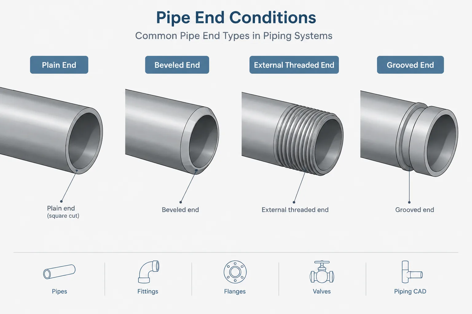
Common pipe end descriptions include:
- Plain end: An end without threads or a formed coupling groove.
- Beveled end: An end machined or cut for a butt-weld joint.
- Threaded end: An end carrying external pipe threads.
- Grooved end: An end prepared with a groove for a compatible mechanical coupling system.
These terms do not independently define every feature needed to fabricate the connection. For example, calling an end beveled does not establish the complete weld-joint preparation. The applicable project specification, welding documentation, material requirements, and approved fabrication details must supply the remaining information.
End Condition Is Not the Same as Joint Type
End condition and joint type are closely related, but they are not interchangeable terms. The end condition describes the component. The joint type describes the assembled connection between components.
A beveled pipe end may form part of a butt-weld joint. A threaded pipe end may be assembled into a fitting with internal threads. A grooved pipe end may be joined by a coupling containing housing segments and a gasket. A plain pipe end can be used in more than one joining arrangement, depending on the selected components and fabrication method.
This distinction is important in CAD databases. A port labeled only as “welded” may not tell the designer whether the modeled connection is butt-welded, socket-welded, or part of another welded assembly. Connection properties should be specific enough to support catalog selection, isometric output, material reporting, and model validation.
Comparison of Common Pipe End Types
| End type | Typical connection concept | Important CAD or documentation issue |
|---|---|---|
| Plain end | Used with a compatible fitting, coupling, socket, or fabrication detail | Do not assume that an unmodeled end treatment requires no preparation |
| Beveled end | Butt-weld connection | Control the weld reference plane separately from optional bevel graphics |
| Threaded end | External threads engaging an internally threaded component | Account for makeup rather than placing components at arbitrary visible endpoints |
| Grooved end | Mechanical coupling around compatible grooved components | Model or reserve the coupling envelope and verify the required end spacing |
Plain Ends
“Plain end” generally means the end is not threaded or grooved. It should not automatically be interpreted as a finished, square-cut end ready for every possible joining process. The required cut quality, squareness, cleaning, deburring, or other preparation depends on the intended connection and governing project documents.
Plain ends often appear deceptively simple in a model because the pipe solid terminates at a flat plane. That plane may represent a cut location, a fitting engagement reference, or merely the end of simplified geometry. Designers should verify how the project catalog interprets it before using the displayed endpoint to calculate cut length.
Plain-End CAD Checks
- Confirm the receiving component and its connection method.
- Determine whether the pipe enters a socket, sleeve, or coupling.
- Identify whether engagement is represented in geometry or stored as data.
- Keep the visible solid endpoint separate from the controlling fabrication reference when necessary.
Beveled Ends
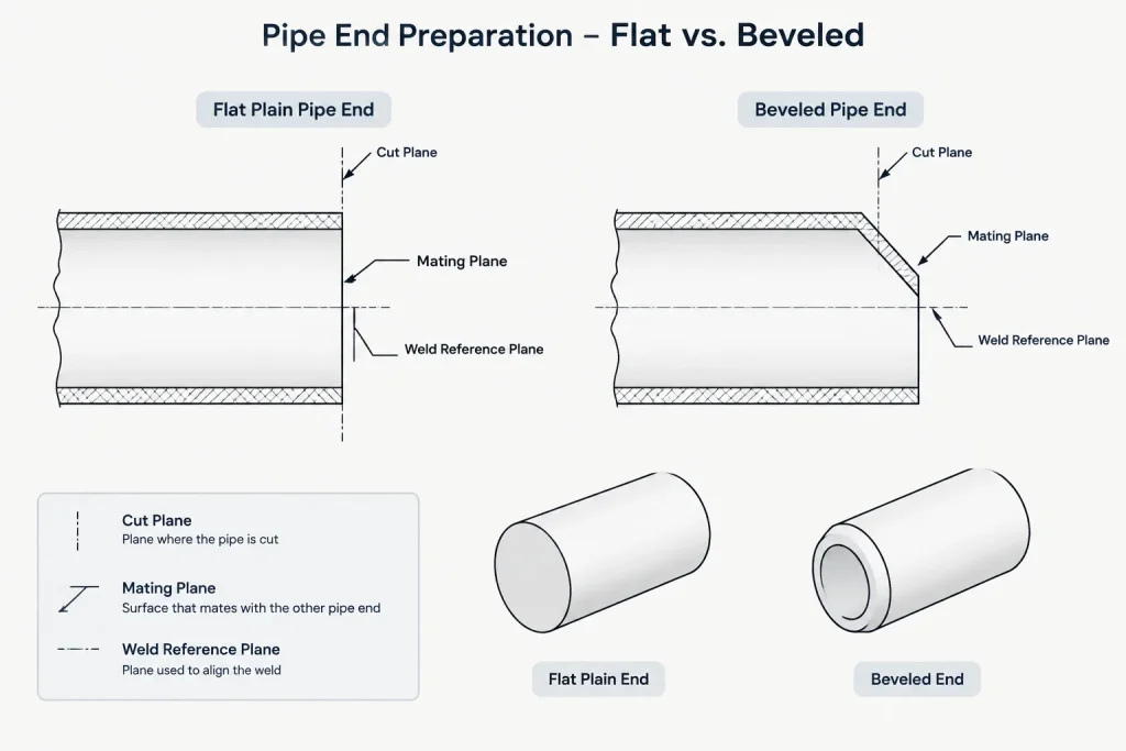
A beveled end is prepared for welding to another compatible end, commonly in a butt-weld arrangement. The complete joint may involve additional features and fit-up requirements that are not practical to model on every pipe segment.
Most piping models simplify bevels because detailed end preparation adds geometry without improving ordinary layout work. The critical model reference is usually the weld or mating plane, not the small edges that depict the preparation. Detailed bevel geometry may be appropriate in fabrication details, shop models, or specialized workflows, but it should be based on controlled requirements rather than a generic visual assumption.
When calculating straight-pipe cut length between butt-weld fittings, use the project’s defined weld-line and component takeoff conventions. Do not subtract a graphical bevel merely because it appears in a detailed component model.
Threaded Ends
A threaded end has external threads intended to engage compatible internal threads. The assembled position is influenced by thread form, component geometry, manufacturing variation, sealant practice, and required makeup. As a result, the pipe’s physical end generally does not behave like a simple face-to-face connection plane.
CAD systems may represent threaded joints with an insertion point or nominal engagement value rather than modeled helical threads. This is usually preferable for plant-layout models because real thread geometry can make files unnecessarily complex.
For nipples and threaded pipe segments, distinguish among overall supplied length, exposed length after assembly, and the portion engaged within adjoining components. A model showing only the visible distance between fittings is not necessarily a pipe cut or purchase length.
Grooved Ends
A grooved pipe end contains a formed or machined feature that works with a compatible mechanical coupling. The connection is an assembly rather than a direct end-to-end fusion of two pipe solids. Its physical envelope can include the coupling housing, gasket region, and fastening hardware.
Grooved systems require coordinated components. A generic groove symbol or appearance does not prove compatibility among the pipe, coupling, fitting, material, wall, and service conditions. Product-specific and project-specific requirements must be verified.
In CAD, the coupling should not disappear into a simple line between pipe ends when its envelope matters for clearance. The model should also preserve the intended component spacing and connection references rather than forcing the pipe solids together for visual neatness.
Mixed-End Components
Not every component has the same preparation at both ends. An adapter may have a threaded end on one side and a weld or grooved connection on the other. A fabricated spool can also contain different terminal conditions.
Catalog records should therefore assign connection properties by port, not only by component name. A general description such as “threaded adapter” may be insufficient if it does not identify which port has external threads, which has internal threads, and what connection exists at the opposite end.
Port-specific data also supports correct component replacement. Swapping a mixed-end adapter end-for-end may change the physical connection even if its overall envelope appears symmetrical.
How End Types Affect CAD Workflow
Component Placement
Each connection needs a meaningful reference point or plane. Butt-weld components commonly connect at weld planes, while threaded and socket-type arrangements may rely on engagement references. Grooved joints require references that maintain the intended relationship among pipe ends and coupling geometry.
Pipe Cut Length
Centerline routing length is not automatically equal to pipe cut length. Fitting takeoffs, socket engagement, threaded makeup, joint gaps, and field-fit allowances may all affect the final value. End-type rules should be built into the fabrication workflow instead of inferred from screen measurements.
Isometric Symbols and Notes
An isometric may show connections symbolically rather than depicting the actual end preparation. Weld symbols, joint markers, component descriptions, and notes should agree with the model and piping specification. A simplified line ending is not sufficient evidence of the intended pipe end.
Material Takeoff
The material description should communicate whether special end preparation is supplied with the item or performed during fabrication. This affects purchasing, shop operations, and inspection. Avoid creating duplicate materials solely because two CAD symbols look different if the purchased product is actually the same; conversely, do not combine items when their required end conditions differ.
A Practical End-Type Review
Before issuing a model, isometric, or material report, review each non-flanged connection with the following questions:
- What is the end condition on each connected component?
- Are the two ends compatible under the project piping specification?
- Does the CAD connection property match the physical joint?
- Is the controlling location a face, weld plane, cut plane, or engagement reference?
- Does the pipe cut length include the correct joint assumptions?
- Is a coupling, sleeve, fitting, or other separate item required in the material takeoff?
- Does the connection create an external clearance envelope that must be coordinated?
- Are any end details provisional pending vendor, shop, or field information?
Use End Types as Controlled Data
Pipe end types should be treated as engineering and fabrication data, not merely as linework. Detailed graphics can be useful, but they do not replace a correctly configured port, catalog entry, piping specification, or material description.
A reliable workflow starts with the intended joint, identifies the required condition at each component end, and then applies the appropriate placement and cut-length rules. That approach keeps the CAD model, isometric, fabrication information, and material takeoff aligned—even when the visible pipe geometry remains intentionally simple.