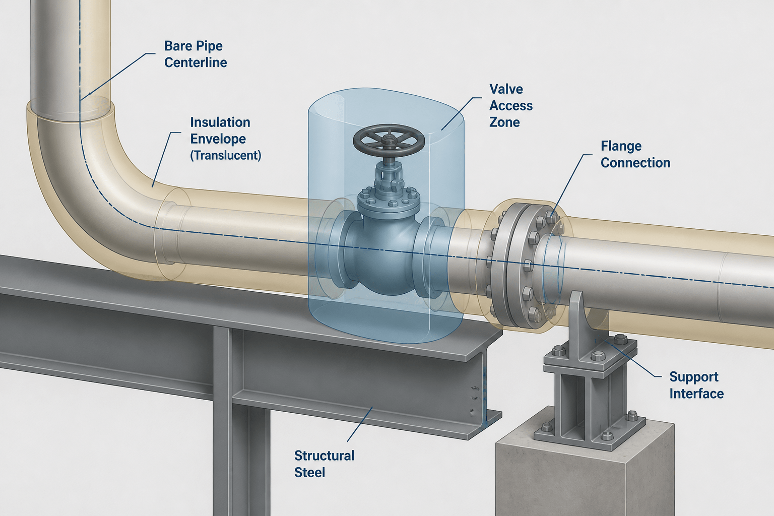
Insulated piping requires more than a centerline and a pipe-size callout. CAD details must help reviewers distinguish the bare pipe from the finished envelope, identify access zones, and understand where insulation interacts with supports, equipment, and attachments.
Use this guide alongside PipeSTD reference material for pipe dimensions, pipe schedules, fitting geometry, and flange references. Those resources describe underlying piping components; the project insulation specification controls the finished insulated condition.
Insulation changes the way a piping system is represented, coordinated, and checked in CAD. The pipe centerline may remain unchanged, but the finished outside surface becomes larger, access requirements change, and supports or attachments may need special interfaces. A drawing that shows only the bare pipe can therefore hide important coordination problems.

This guide explains a practical workflow for insulated piping CAD detailing. It focuses on drawing conventions, clearance zones, support interfaces, and insulation breaks rather than prescribing universal dimensions. Always use the project’s piping material specification, insulation specification, equipment requirements, and applicable design rules for final values.
Why insulation must be modeled as more than a note
On a simple line diagram, insulation may appear as a line class attribute or a short abbreviation. In a layout or detail drawing, however, insulation affects physical space. It can influence:
- Available clearance between adjacent lines and structures
- Access to valves, flanges, drains, vents, and instruments
- Support width and the location of clamps, shoes, guides, or other attachments
- Clearance at platforms, ladders, handrails, doors, and removable equipment
- Transitions at equipment nozzles, pipe penetrations, and deliberate insulation breaks
- The interpretation of pipe dimensions in a CAD model or fabrication drawing
The key drafting principle is to distinguish the pipe from its insulation. The pipe centerline and nominal pipe geometry remain the basis for routing, while the insulation envelope represents the installed outside boundary used for spatial coordination.
Start with the insulation design basis
Before editing a model or adding an insulation layer, identify what the line is supposed to represent. Useful inputs commonly include the line list, piping material specification, insulation class or code, operating condition, heat conservation or personnel-protection requirement, tracing requirement, and project drawing conventions.
Do not infer an insulation arrangement solely from pipe size or service name. Two lines with similar dimensions may have different insulation, jacketing, tracing, removable-cover, or access requirements. The controlling project documents should define the insulation system and any areas where it is intentionally omitted.
It is also important to confirm whether the available reference table describes bare pipe dimensions or an assembled component. Pipe dimension tables, fitting references, and flange pages normally describe the metallic component, not the finished insulated envelope. Use those resources for the underlying pipe and fitting geometry, then apply the project insulation information separately.
Represent the insulated envelope in CAD
There are several useful levels of representation. The appropriate method depends on the drawing purpose and the capabilities of the CAD or plant-design system.
| Drawing purpose | Useful representation | Primary check |
|---|---|---|
| General arrangement | Pipe centerline with a visible or selectable insulation envelope | Overall spatial clearance |
| Detail or section | Pipe wall, insulation layer, and outer covering shown separately | Interface construction and access |
| Isometric or spool documentation | Insulation status and break locations identified by project convention | Fabrication and field interpretation |
| Support detail | Pipe, insulation, support member, and any protection interface shown together | Load path and insulation continuity |
For a 2D layout, a dedicated insulation layer or offset line can make the envelope visible without confusing it with the pipe centerline. In a 3D model, an insulation object or clearance volume may be more useful. Keep layer names, colors, lineweights, and visibility states consistent so reviewers can tell whether they are checking the pipe, insulation, cladding, or a temporary clearance aid.
Avoid presenting insulation as a solid pipe replacement. If the insulation layer obscures the actual centerline, fittings, or connection points, reviewers may lose the information needed to check the piping system.
Coordinate clearances using the finished envelope
Clearance checks should consider the condition that people, tools, insulation, and maintenance activities will encounter. For example, two bare pipe centerlines may appear adequately separated while their insulated surfaces conflict. The same issue can occur between an insulated line and a beam, wall, cable tray, platform edge, or access opening.
Use the following sequence during layout review:
- Confirm the pipe centerline and component orientation.
- Apply the correct insulation envelope to straight pipe and fittings.
- Check the envelope against nearby lines, steel, equipment, and building elements.
- Identify components that require operation, removal, inspection, or routine access.
- Check whether insulation thickness, jacketing, tracing, or removable covers changes the local envelope.
- Record conflicts separately from code or process clearances so each issue has a clear owner.
Do not use a single global offset when the project includes different insulation systems. Elbows, tees, reducers, valves, and flanged joints may require different graphic treatments or locally enlarged access zones. If the CAD system cannot model those differences, use detail callouts and review notes rather than implying false precision.
Show insulation breaks deliberately
An insulation break is a design condition, not merely a gap in a drawing line. Common locations may include certain flanged connections, valve operators, equipment interfaces, instrument connections, removable covers, support interfaces, or areas requiring inspection. The exact treatment depends on the project specification and the function of the component.
When a break is required, show enough information for the next discipline or construction team to understand its intent. A useful detail may identify:
- The start and end of the insulation or cladding
- Whether the break applies to the insulation, weatherproofing, heat tracing, or all of them
- Whether a removable cover or maintenance access is required
- How the break relates to a flange, valve, instrument, nozzle, or support
- Which project note or specification controls the final construction
Do not assume that every flange, valve, or support should be left exposed. The drawing should reflect the specified arrangement, not a generic drafting habit.
Detail supports without creating an insulation conflict
Supports are one of the most frequent locations where insulation continuity and mechanical support requirements intersect. A support may carry the pipe directly, connect through a shoe or saddle, use a clamp arrangement, or require a specialized thermal interface. The correct arrangement depends on temperature, movement, load transfer, corrosion protection, and the project support standard.
In CAD, show the relationship between the pipe and support clearly. A support detail should answer whether the support contacts the pipe, the insulation system, a protective jacket, or a dedicated attachment. It should also make clear where sliding, guiding, or anchoring is intended if those functions apply.
Do not draw insulation continuously through a support merely because it is visually simple. Conversely, do not remove insulation from a support region without identifying the required protection or closure. Coordinate the support detail with the insulation detail so the model does not show two incompatible conditions.
Handle valves, flanges, and equipment connections
Component access is often more important than the straight-run envelope. A valve body may fit within the line corridor while its handwheel, actuator, chain operator, removable bonnet, or maintenance path conflicts with adjacent steel. Flange bolt-up and gasket access also require a practical working zone, even when the flange itself is correctly positioned.
At equipment connections, distinguish the pipe connection from the insulation termination. Insulation may stop before a nozzle, continue toward the equipment, or use a removable arrangement. The equipment vendor’s interface information and the project insulation specification should control the drawing.
For CAD review, use enlarged details where a general arrangement cannot show the termination clearly. A small section or elevation can prevent ambiguity around flange covers, valve access, nozzle insulation, and nearby supports.
Common drafting errors to catch before issue
- Using bare-pipe spacing: The layout is checked from centerline to centerline, but the finished envelope is not reviewed.
- Hiding the centerline: The insulation graphic makes it difficult to locate the actual pipe axis or connection point.
- Applying one insulation offset everywhere: Special components and removable areas are treated like straight pipe.
- Ignoring access volume: The line fits geometrically, but valves, flanges, instruments, or equipment cannot be operated or removed.
- Leaving support interfaces undefined: The pipe, support, insulation, and protective elements appear to occupy the same space.
- Failing to synchronize drawings: The plan, section, isometric, support detail, and insulation notes show different break locations.
- Overstating precision: A generic CAD envelope is presented as a construction dimension without project confirmation.
A practical final review checklist
Before issuing an insulated piping layout or detail, review the drawing in this order:
- Verify that the line’s insulation status and governing project information are identified.
- Confirm that the pipe centerline, component geometry, and insulation envelope are distinguishable.
- Check finished-envelope clearance to adjacent piping, steel, equipment, and building elements.
- Review operation, removal, inspection, and personnel-access zones.
- Check insulation breaks at components, equipment interfaces, supports, and penetrations.
- Confirm that support details preserve the intended mechanical and insulation functions.
- Compare plans, sections, isometrics, support drawings, and notes for consistent break locations.
- Replace generic assumptions with project-controlled details wherever the condition is safety-critical or construction-sensitive.
Good insulated piping CAD detailing does not require every line to be modeled at maximum graphic complexity. It requires the drawing to show the information needed for the decision being made. Keep the pipe geometry authoritative, represent the finished envelope where space matters, and use focused details at supports, access points, and insulation breaks. This approach makes CAD reviews faster while reducing the risk that a visually clean drawing hides a practical installation problem.
How to use this guide with piping references
The most reliable workflow separates three kinds of information: the underlying pipe and component geometry, the insulation and cladding arrangement, and the access or support condition around the assembly. Keeping these layers distinct makes a CAD review easier to follow and reduces the chance that an insulation graphic will be mistaken for the actual pipe boundary.
When checking a layout, begin with the authoritative pipe centerline and component references. Then apply the project-controlled insulation information and review the resulting envelope against adjacent piping, structural elements, equipment, and access paths. PipeSTD pages on piping terminology can also help standardize descriptions for fittings, supports, joints, and component interfaces across drawing notes.
CAD coordination questions to resolve early
- Is the drawing showing bare pipe geometry, an insulation envelope, or both?
- Are insulation breaks controlled by a project note, specification, equipment interface, or support detail?
- Can operators and maintenance personnel reach the components shown?
- Does the support arrangement preserve the intended load path and insulation treatment?
- Do plans, sections, isometrics, and support details show the same interface condition?
For teams exchanging drafting resources, a consistent CAD and DWG reference workflow is useful for layer naming, visibility control, detail reuse, and review coordination. Templates should improve consistency without disguising project-specific insulation requirements.
Frequently asked questions
Should insulation replace the pipe geometry in a CAD model?
No. The pipe centerline and component geometry should remain identifiable. The insulation envelope should be represented as a separate layer, object, offset, or coordinated detail so reviewers can check both the piping arrangement and the finished outside condition.
Should clearance be checked from the pipe centerline?
Centerline geometry is the starting point for routing, but spatial coordination should also consider the finished insulated envelope and any local access, operation, removal, or maintenance requirements.
Does every valve or flange require an insulation break?
No. The treatment depends on the project insulation specification, component function, access needs, and equipment or support interfaces. Do not apply a generic exposed-component convention without project confirmation.
How should an insulation break be shown?
Identify the termination location and clarify whether the break affects insulation, cladding, tracing, a removable cover, or another related system. Reference the controlling project note or specification when the drawing alone cannot define the construction.
What should a support detail communicate?
It should make the relationship between the pipe, insulation, support member, and any protective or thermal interface clear. The detail should also identify the intended support function where movement, guiding, or anchoring is relevant.
Are pipe dimension tables enough to detail insulated piping?
No. Pipe and fitting tables provide the underlying component geometry, while insulation requirements come from project-controlled documents. Combine the two sources rather than treating a bare-component dimension as the finished envelope.