
Piping line numbers give each process or utility line a controlled identity across engineering documents and CAD deliverables. They help connect the P&ID, line list, piping specification, model, and drawing, but their codes are not universal.
This guide explains how to decode a line number without guessing, check it against authoritative project records, and maintain reliable references during CAD drafting, revision, and review. For related terminology, see the reference on piping terminology and the site’s resources for CAD and DWG workflows.
A piping line number is the identifier assigned to a process or utility line so that engineers, designers, fabricators, and operations teams can refer to the same system consistently. It may appear on a P&ID, line list, piping specification, isometric drawing, equipment interface drawing, and 3D model.
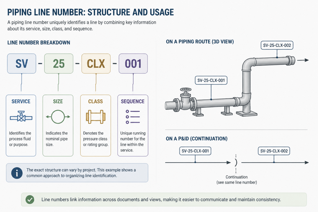
Line numbers are often mistaken for simple labels. In practice, they connect several types of engineering information. Depending on the project convention, a single identifier may communicate the nominal pipe size, fluid or service code, piping class, insulation requirement, sequence number, or other attributes. The exact format is project-specific, so a drafter should never infer a line’s complete design basis from the number alone.
This guide explains how to interpret line numbers safely and use them as a reliable CAD coordination tool without replacing the project’s line list, piping material specification, or controlled drawing notes.
What information does a piping line number contain?
There is no universal line-number format used on every project. A typical identifier is made from several fields separated by hyphens, slashes, or other delimiters. The fields may be arranged differently from one company or facility to another.
| Possible field | What it may identify | How to use it |
|---|---|---|
| Size | Nominal pipe size or size designation | Use as an initial lookup key, then verify against the line list and drawing. |
| Service code | Fluid, utility, or process service | Compare with the P&ID, equipment connections, and process documentation. |
| Piping class | Material, component, rating, and joining requirements | Check the controlled piping material specification before selecting components. |
| Insulation or tracing code | Thermal insulation, personnel protection, heat tracing, or related treatment | Coordinate with insulation, support, and access details. |
| Sequence or line identifier | A unique reference for the individual line | Use it to maintain continuity across drawings and model areas. |
Some projects place the piping class in a separate column rather than inside the line number. Others use line numbers that contain only a unique sequence and rely on a separate line list for all technical attributes. The format itself is not proof of the design requirements.
Why line numbers matter in CAD work
In a CAD or plant-design workflow, the line number is the main connection between design intent and geometry. It helps the user confirm that a modeled or drafted pipe belongs to the correct service and specification before adding fittings, valves, supports, or insulation.
Correct line-number use also helps with:
- Tracing a line between a P&ID, general arrangement drawing, and isometric.
- Confirming that connected pipe segments belong to the same design system.
- Assigning the correct piping class or material specification.
- Organizing model properties, drawing references, and spool or fabrication information.
- Finding discrepancies during model review and drawing checking.
- Keeping revisions synchronized across multiple deliverables.
A line number does not replace a dimension, elevation, coordinate, valve tag, or equipment tag. It is an identity and information-management tool, not a complete geometric description.
How to read a line number step by step
1. Find the project line-numbering convention
Start with the project drafting standard, CAD manual, or line-list instructions. Look for an example that identifies each field and delimiter. Do not rely on a familiar format from another project; similar-looking codes can have different meanings.
Record whether the identifier is case-sensitive, whether leading zeros matter, and whether optional fields are used. Also check how revisions, temporary lines, demolition work, and future connections are represented.
2. Separate the identifier into fields
Read the line number from left to right and split it at the project-defined separators. Label each segment before interpreting it. This prevents a common mistake: assuming that every early field represents pipe size or that every final field is a sequence number.
For example, a project may use one segment for service, another for size, and another for class. A different project may put size first and store insulation information in a separate database field. The visual pattern can be similar while the meaning is different.
3. Cross-check the result against the line list
The line list is normally the best place to verify the complete record for a line. Compare the line number with the listed service, nominal size, piping class, design conditions, insulation status, and connected equipment or location information where applicable.
When the line number and line list disagree, do not silently correct the drawing. Flag the discrepancy according to the project review process. It may indicate a revision issue, a copied annotation, a split line, or an intentional change in specification.
4. Confirm the P&ID relationship
Follow the line number on the P&ID and confirm its direction, branches, valves, instruments, and equipment connections. A line number can be correct while the geometry is wrong. For example, the label may have been copied to a neighboring line or placed on the wrong side of a branch.
Pay attention to line breaks and continuation symbols. A line that continues onto another drawing may retain its identity, while a branch, service change, or specification break may require a new line number. The project’s P&ID rules determine how those transitions are recorded.
Using line numbers when creating or editing CAD drawings
When starting a drawing, enter the line number from a controlled source rather than typing it from memory. If the CAD system supports attributes or object data, store the identifier as a searchable property instead of relying only on visible text.
For each line, check the following before detailing components:
- Line number matches the current design source.
- Service and flow direction agree with the P&ID.
- Nominal size is consistent at each continuous segment.
- Piping class is verified against the current specification.
- Reducers, branches, valves, and specialty items are identified at any specification or size change.
- Insulation, tracing, and heat-conservation notes are coordinated with the line requirements.
- Continuation references are clear where the line crosses drawing boundaries.
Use consistent text placement and layer conventions so line numbers remain readable without obscuring dimensions, weld symbols, centerlines, or equipment tags. On crowded isometrics, a leader or continuation note may be preferable to placing text directly over the pipe graphic.
Common line-numbering mistakes
Copying a nearby line number
Parallel lines often have similar geometry, making copied annotations a frequent source of errors. After copying a route or view, verify every identifier against the source documents instead of changing only the size or service text.
Treating the line number as a complete specification
A code may suggest a piping class, but it does not authorize the drafter to choose a valve, flange, gasket, or fitting from memory. Use the project piping material specification and the authoritative component reference data.
Ignoring specification breaks
A change in service, material, temperature requirement, joining method, or other controlled attribute may require a new line number or a clearly documented break. The correct treatment depends on project rules and should be resolved before fabrication information is issued.
Leaving stale identifiers after a revision
When a line is rerouted, split, deleted, or reclassified, update all affected views and references. Search the drawing set or model for the old identifier, including notes, continuation symbols, layer names, and extracted reports.
A practical review checklist
Before issuing a CAD drawing, perform a line-number review separate from the geometric check:
- Is every process or utility line identified?
- Does each visible identifier match the current line list?
- Are line numbers placed on the correct physical line?
- Are branches and continuation points treated according to the project convention?
- Do size, service, and piping class agree across the P&ID, model, and drawing?
- Are old numbers removed from copied views and revised areas?
- Can another reviewer search for the line and trace it through the drawing set?
Used consistently, piping line numbers provide a dependable link between process documentation, piping specifications, and CAD deliverables. The most important habit is to treat the identifier as a controlled reference: decode it using the project convention, verify it against authoritative records, and update it everywhere when the design changes.
How line numbers fit into the piping documentation system
A line number is most useful when treated as a cross-reference rather than an isolated code. The identifier can lead a reviewer from a drawing to the line list, from the line list to the piping material specification, and from the P&ID to the corresponding modeled or drafted geometry.
That relationship also explains why line-number verification should be separate from ordinary drafting checks. A line may look correctly routed while carrying the wrong identifier, or the identifier may be correct while the route, branch, or specification break is inaccurate. Checking both the reference data and the physical representation reduces the chance of carrying an error into later deliverables.
Use the right reference for each question
- Use the project convention to interpret the structure and separators in the identifier.
- Use the line list to confirm the complete line record and associated attributes.
- Use the P&ID to verify service relationships, branches, valves, instruments, and equipment connections.
- Use the piping material specification before selecting pipe components, fittings, flanges, or valves.
- Use the CAD model or drawing to confirm that the identifier is attached to the correct physical line.
When component selection is involved, the line number should be the starting reference—not the sole design authority. Pair it with the project specification and controlled component data. Related references on pipe dimensions and schedules, pipe fittings, and pipe flanges can help organize the next stage of the check.
Make line-number review searchable
Searchable CAD properties, consistent attributes, and controlled text styles make it easier to find stale identifiers after a revision. A useful review should search visible labels as well as continuation notes, model properties, extracted reports, and copied drawing views. This is especially important when a route is split, a branch changes, or a specification boundary is introduced.
For drafting teams, a simple responsibility rule is effective: the person creating or revising the geometry verifies the line’s source record, while the checker confirms consistency across the related documents. The exact approval process remains project-specific, but the principle is the same—every identifier should be traceable to a controlled source.
Related piping reference topics
Line-number work often overlaps with piping isometric drawings, P&ID interpretation, and piping material specifications. These references provide useful context when a line number must be traced from process intent to physical layout and component selection.
Frequently asked questions
Is there one universal piping line-number format?
No. Line-number structure is established by the project, company, or facility convention. Similar-looking fields can have different meanings, so the applicable drafting standard or line-list instructions should be checked first.
Can a line number replace the piping specification?
No. A line number may point to a piping class or related record, but it does not by itself authorize selection of pipe, fittings, flanges, valves, gaskets, or other components. Verify those choices against the controlled project specification.
What should be checked when a line number and line list disagree?
Do not silently overwrite either record. Flag the discrepancy through the project review process and determine whether it results from a revision, copied annotation, split line, specification break, or intentional design change.
Where should line numbers be stored in CAD?
When the software supports it, store the identifier in searchable object data or an attribute as well as displaying it in the drawing. This makes model and drawing searches more dependable than visible text alone.