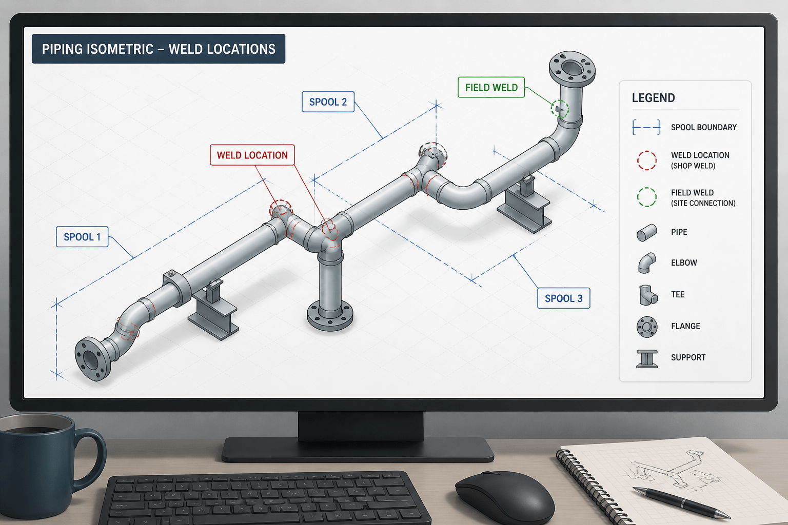
Piping isometric weld symbols connect the drawing to fabrication, erection, and inspection activities. A clear symbol should help the reader locate the joint, understand where the work occurs, and find the project document that controls detailed welding requirements.
This guide presents a practical CAD review approach for tracing weld annotations, checking spool boundaries, confirming weld identification, and spotting drafting errors before an isometric is issued.
Weld symbols on a piping isometric do more than show that two components are joined. They communicate how the connection is intended to be fabricated, where the work will occur, and which notes or quality requirements apply. A symbol may identify a shop weld, field weld, socket-welded fitting, butt weld, or a special connection that requires a project-specific note.

Correctly reading piping isometric weld symbols is important because a drawing can appear geometrically correct while still creating a fabrication, erection, or inspection problem. The first step is to understand the project legend and drawing conventions. The guidance below explains a practical review method without replacing the governing project standard, piping material specification, weld procedure, or approved drawing legend.
What weld information appears on a piping isometric?
A piping isometric commonly combines several types of weld information:
- Weld location: The symbol is associated with a joint, component end, branch connection, or field connection.
- Weld category: A drawing may distinguish shop welds, field welds, closure welds, tie-in welds, or other project-defined categories.
- Joint type: The graphical symbol or accompanying note can indicate a butt-welded, socket-welded, fillet-welded, or special joint.
- Identification: A weld number or joint tag may link the isometric to a weld map, inspection record, spool sheet, or material tracking system.
- Additional requirements: Notes can identify examination, heat treatment, purge requirements, consumables, or other controls. These requirements must come from the approved project documents.
Not every project uses the same abbreviations or graphic conventions. Some companies use a distinctive flag or letter for a field weld, while others use a weld list, color layer, or separate column in the material and fabrication data. Treat the drawing legend as the controlling interpretation for that project.
Shop welds and field welds: the basic distinction
The most important distinction is often whether the weld is made during shop fabrication or during field erection. A shop weld joins parts before the spool or fabricated assembly reaches the site. A field weld is completed at the installation location, usually to connect spools, equipment nozzles, site-fabricated sections, or tie-in points.
| Weld category | Typical drawing purpose | CAD review question |
|---|---|---|
| Shop weld | Defines a joint included in a fabricated spool or shop assembly. | Is the joint located within the intended spool boundary? |
| Field weld | Identifies a connection reserved for site installation or final assembly. | Can the joint be accessed, aligned, and welded at the site? |
| Closure weld | Marks a final connection needed to close a routed section or assembly. | Has the weld been left in a practical location rather than trapped by surrounding steel? |
| Tie-in weld | Shows a connection to existing, operating, or separately constructed piping. | Is the tie-in reference clear, and is the connected system correctly identified? |
The exact names vary. A field weld is not automatically a tie-in weld, and a closure weld is not necessarily the only field weld on a line. Use the project terminology rather than assuming that similar labels have identical meanings.
How to read a weld symbol on an isometric
1. Start with the drawing legend
Before interpreting an unfamiliar mark, locate the isometric legend, general notes, or drafting standard reference identified by the project. Confirm how the drawing represents welds, breaks, continuation lines, field-work symbols, and weld numbers. This prevents a common error: applying a familiar symbol convention from another company to a drawing that uses a different convention.
2. Find the physical joint
Trace the leader or symbol to the actual connection. Determine whether it points to a pipe-to-pipe butt joint, a fitting end, a flange weld, a branch connection, a valve-end connection, or another component interface. On a crowded isometric, a leader can appear to point to a nearby line or dimension rather than the intended joint.
Use the line geometry, component tags, and break points together. Do not identify a weld solely from its position on the page. A symbol beside a flange may refer to the flange-to-pipe weld, the flange face, or a nearby field connection depending on the leader arrangement and project convention.
3. Read the symbol and its attached data
After locating the joint, read the graphical symbol, weld number, suffix, tail note, and any associated schedule or weld-list reference. A symbol may describe the general joint type, while the weld list supplies the inspection category or fabrication status. If the information conflicts, stop and resolve the discrepancy through the project document-control process rather than guessing.
4. Check both ends of the connection
Many piping components have two or more possible weld locations. A reducer, branch fitting, valve, flange, or instrument connection can be misread if the review focuses only on the component label. Confirm which end is welded, which end is flanged or threaded, and whether the connection agrees with the piping material specification.
Weld symbols and spool boundaries
Weld information should agree with the way the line is divided into spools or fabricated assemblies. A spool drawing typically contains a defined group of pipe and fittings, while field connections separate that spool from another assembly or from site-installed equipment.
During review, compare the weld marks with:
- Spool break locations and spool identification numbers.
- Pipe cut lengths and fitting orientation.
- Flange and gasket interfaces that are not welded joints.
- Support locations, guides, shoes, and nearby structural steel.
- Access required for welding, examination, coating, and insulation.
A field weld placed immediately beside a support, elbow, branch, or equipment nozzle may be difficult to execute even if the geometry is technically connected. The isometric should provide enough information for the fabricator and installer to understand the intended sequence, while detailed constructability review may require model views, arrangement drawings, or site information.
Common CAD mistakes involving weld symbols
Symbols detached from the joint
Leaders may move during editing, especially when a component is stretched, rotated, or replaced. A symbol that no longer terminates at the correct joint can create an ambiguous fabrication instruction. Use object snaps or a controlled annotation workflow where possible, then inspect the final plotted drawing rather than relying only on the model view.
Field-weld marks omitted after revisions
When a spool boundary changes, the field-weld symbol may be deleted, duplicated, or left at the old location. Recheck all affected weld numbers and compare the revised isometric with the previous approved issue using the project revision procedure.
Weld numbers duplicated or skipped
Weld identification should be traceable within the drawing set and any associated weld register. Duplicate numbers can cause inspection records to be assigned to the wrong joint. Skipped numbers may be acceptable in some numbering systems, but unexplained gaps should be checked rather than silently corrected.
Weld symbols confused with connection symbols
A flange, threaded connection, socket connection, or mechanical coupling may be shown using a separate convention from a welded joint. Do not add a weld mark simply because two components meet. Verify the component end type against the line specification and the fitting or flange reference used by the project.
A practical CAD checking workflow
- Review the legend: Confirm symbols, abbreviations, weld categories, and numbering rules.
- Trace the line: Follow the piping from one endpoint to the other and identify every physical joint.
- Compare the isometric and model: Confirm that symbols remain attached to the correct locations after routing or component changes.
- Check spool logic: Make sure shop and field welds agree with spool breaks and fabrication boundaries.
- Review access: Look for nearby steel, equipment, insulation, supports, or other piping that could obstruct the intended work.
- Verify traceability: Compare weld numbers with the weld list, spool sheet, or inspection documentation required by the project.
- Plot and inspect: Check line weights, leader clarity, overlapping notes, and symbol visibility at the issued drawing scale.
Final checks before issuing the drawing
Before release, confirm that each weld mark answers three questions: which joint is affected, where is the work performed, and what document controls the detailed requirement? If a reader must infer any of these from geometry alone, the annotation may need improvement.
Weld symbols are only one part of piping fabrication documentation. They work with the piping isometric, spool drawing, piping material specification, weld register, inspection plan, and applicable project procedures. Keep those references consistent, and treat unresolved symbol conflicts as document-control issues rather than drafting details to be guessed in CAD.
What a weld symbol can—and cannot—tell you
A weld mark is an instruction in the drawing system, not a substitute for the approved welding and inspection documentation. It may identify the joint location, connection category, or fabrication status, while the governing project documents define the detailed procedure and acceptance requirements.
This distinction is useful when reviewing a piping isometric against a three-dimensional model or a spool drawing. The drawing should make the intended joint and its traceability clear, but detailed decisions about welding, examination, heat treatment, consumables, and related controls should be verified against the applicable project documents.
How to review weld annotations efficiently
- Review by line: Follow each piping run from its endpoint and inspect every component interface where a weld may occur.
- Review by spool: Compare weld marks with spool boundaries and fabrication breaks so that shop and field work are not inadvertently reversed.
- Review by document link: Confirm that weld numbers and notes can be matched to the required weld list, spool sheet, or inspection record.
- Review the plotted sheet: A symbol that looks clear in the CAD workspace may overlap a dimension, leader, or component tag when printed or issued electronically.
For related drafting checks, compare the isometric with the piping isometric drawing guide and use the pipe spool drawing guide when reviewing fabrication boundaries and spool identification.
Frequently asked questions
What is the first step when reading a weld symbol on a piping isometric?
Start with the project drawing legend and general notes. Confirm how the project represents weld categories, field connections, weld numbers, leaders, and related annotations before interpreting an individual mark.
Are all field welds tie-in welds?
No. A field weld is generally identified by where it is performed, while a tie-in describes a connection to existing, operating, or separately constructed piping or equipment. The project terminology controls the exact meaning.
Why should weld symbols be checked against spool boundaries?
Spool boundaries indicate how piping is divided for fabrication and installation. If a weld symbol does not agree with those boundaries, the drawing may cause confusion about whether the joint belongs in the shop or must be completed in the field.
What should be done when a weld symbol conflicts with the weld list?
Do not resolve the discrepancy by guessing or silently changing the CAD mark. Record the conflict and obtain clarification through the project document-control process.
Can a piping isometric define the complete welding procedure?
Usually, the isometric identifies the joint and related project references rather than defining every welding and inspection detail. Consult the approved piping, welding, and quality documentation for requirements beyond the drawing annotation.