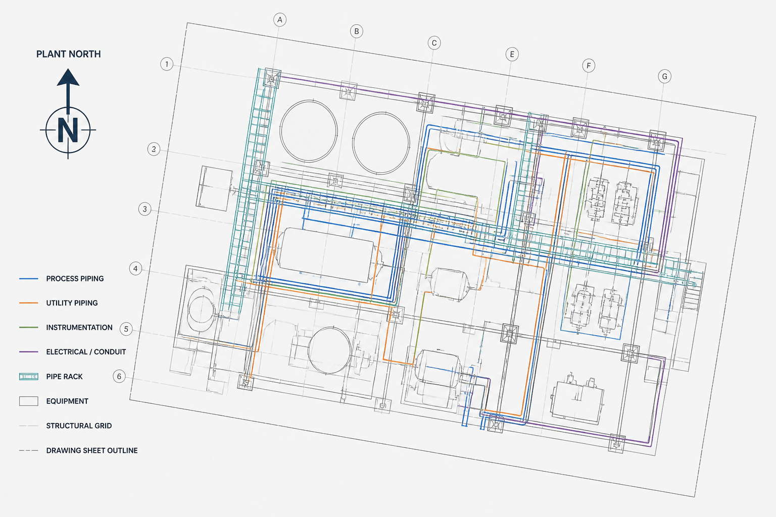
Understanding plant north vs. true north is essential when preparing or reviewing piping CAD drawings. A north arrow may describe the project’s working orientation, geographic direction, coordinate grid, or simply the way a plan is presented on a sheet.
This guide explains how to distinguish those references, verify the controlling orientation, and coordinate rotated piping plans with civil, structural, survey, and other discipline drawings.
Orientation is one of the quiet foundations of reliable piping documentation. A piping plan can contain correct equipment locations, dimensions, and line routes yet still create confusion if its north direction is misunderstood. The same problem can affect coordinates, nozzle orientation, support locations, underground routes, and connections between civil, structural, mechanical, and electrical drawings.
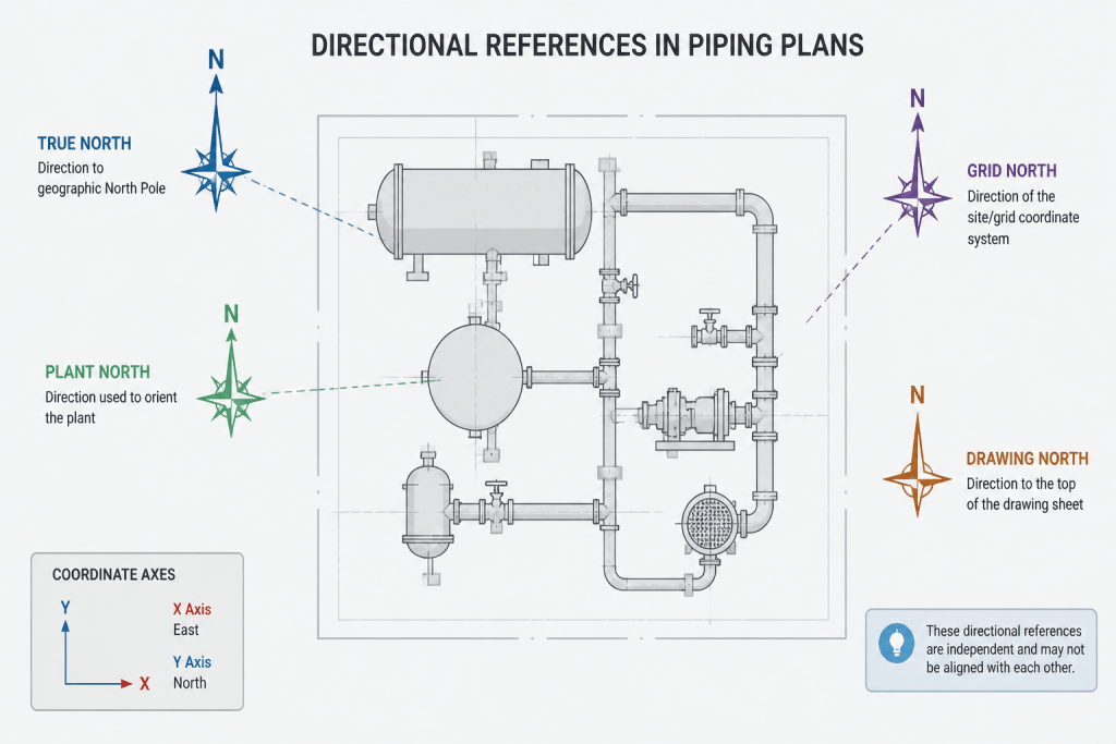
In piping CAD, the word north does not always mean geographic north. Projects may use plant north, true north, project north, grid north, or drawing north for different purposes. These references can be related, but they are not automatically interchangeable. Before editing a plan or creating a new layout, identify which orientation system the project uses and how it is shown.
Why north references matter in piping drawings
Most piping plans are viewed from above, so the plan needs a consistent relationship between the drawing page and the physical plant. That relationship supports several practical tasks:
- Locating equipment and piping in the correct area of the facility.
- Coordinating pipe racks, structures, roads, trenches, and access routes.
- Transferring nozzle and connection directions between plans, elevations, and isometrics.
- Using plant coordinates for survey, construction, and field verification.
- Maintaining consistent orientation across CAD references and discipline models.
An incorrect north reference may not be obvious in a single drawing. The error often appears later when a plan is overlaid with a structural drawing, when coordinates are checked against a survey, or when a field team tries to match a drawing to the physical installation.
Common north terms in plant and piping documentation
| Term | Practical meaning | CAD consideration |
|---|---|---|
| True north | The direction toward geographic North Pole used as a geographic reference. | It may be shown for site or survey coordination, but it is not necessarily the working direction used to lay out a process unit. |
| Plant north | The project-defined north direction used to organize the facility. | It is often the primary orientation for plant plans, equipment locations, and piping coordination. |
| Project north | A north direction established for a particular project, site, or design package. | Confirm whether the project uses this term as a synonym for plant north or as a separate reference. |
| Grid north | The north direction associated with a coordinate grid or mapping system. | It can differ slightly from true north depending on the mapping system and location. |
| Drawing north | The direction placed toward the top or another selected edge of a sheet. | It describes sheet presentation, not necessarily physical site orientation. |
Project documents do not always use these terms consistently. A general arrangement drawing may call a direction “north,” while a civil base file may use a survey or grid reference. Treat the project’s orientation note, coordinate basis, and approved reference drawings as the controlling information.
Plant north is not always the top of the page
A common drafting assumption is that north must point upward on every plan. This is often impractical. Designers may rotate a plan to fit the sheet, improve readability, align a process train, or match an established drawing set. The plan can be rotated without changing the physical model, provided the north arrow and coordinate information remain correct.
In a rotated plan, three directions must be kept distinct:
- Physical north: the project-defined direction in the plant.
- Sheet up: the direction toward the top of the printed or plotted page.
- Model coordinates: the numerical location system used by the project.
Rotating the view should not silently rotate the coordinate system or change the orientation of referenced equipment. In CAD, check whether the drawing uses a rotated view, a transformed reference file, a user coordinate system, or a simple graphical north arrow. These methods can look similar on paper but behave differently during editing and coordination.
How to identify the controlling orientation before drafting
Use a short orientation review before creating or revising a piping plan.
1. Check the title block and general notes
Look for statements defining plant north, project north, coordinate units, grid basis, or drawing rotation. Also check whether the sheet contains a north arrow, key plan, coordinate table, or orientation diagram. Do not infer the reference solely from the arrow’s label; read the surrounding notes.
2. Compare an approved reference drawing
Open an established plot plan, equipment arrangement, or civil base drawing from the same project. Compare the location of recognizable features such as roads, buildings, pipe racks, battery limits, or major equipment. This can reveal whether the current sheet is rotated or whether the referenced file uses a different orientation.
3. Inspect the CAD coordinate basis
Review the origin, axes, units, and coordinate-system settings. Determine whether model coordinates represent plant coordinates, survey coordinates, a local area grid, or only a convenient drafting origin. A local origin can be useful for design, but it should not be presented as a site coordinate without project confirmation.
4. Verify references before attaching them
When attaching external CAD files, check insertion point, units, rotation, clipping, and layer visibility. A reference that appears close to the correct location may still have a wrong rotation or coordinate transformation. Use common control points or known equipment centers to verify the relationship.
Using north correctly in piping plan views
North orientation is especially important when a plan communicates routing rather than only location. A pipe turning east in one view should still correspond to the same physical direction when reviewed against equipment, structures, and access areas.
For each plan, confirm the following:
- The north arrow is visible at the intended plotting scale.
- The arrow agrees with the project’s defined orientation, not merely the page layout.
- Equipment tags, line routes, and coordinates match the approved base drawing.
- Rotated viewports do not obscure or mislead the reader about physical direction.
- Referenced disciplines use the same orientation or clearly identify their transformation.
- Sections and elevations identify their viewing direction when that direction affects interpretation.
For a section, the viewing direction is often more useful than a north arrow alone. A section marker should make clear which way the viewer is looking and which plant directions appear on the sheet. This helps reviewers connect a section to the corresponding plan without guessing.
CAD workflow for a rotated piping plan
A reliable workflow separates model orientation from sheet presentation:
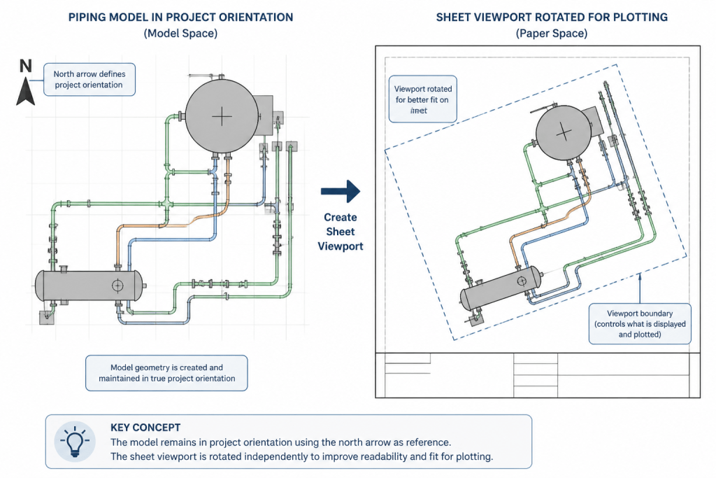
- Establish the project coordinate and north basis from approved information.
- Place or verify the base model using that basis.
- Route and dimension piping in model space without using the sheet edge as a directional reference.
- Create a view or viewport that presents the area clearly on the sheet.
- Place a north arrow that reflects the physical model, not an assumed page-up direction.
- Check coordinate labels, equipment orientation, and reference files after the view is rotated.
- Plot a review copy and compare it with an approved plan from the same area.
Be cautious when using CAD commands that rotate geometry rather than only rotating the view. Rotating the actual model can change coordinates, block insertion behavior, annotation orientation, and the relationship to external references. If model rotation is necessary, document the transformation and apply it consistently.
Common mistakes and how to prevent them
Assuming “up” means north
Prevent this by checking the north arrow and project notes on every plan. A sheet can be intentionally rotated for presentation.
Copying a north arrow from another drawing
A copied symbol may carry the wrong rotation or reference. Use a controlled block or project template, then verify its direction against known geometry.
Mixing survey and plant coordinates
Coordinate values from a survey, civil model, and piping layout may use different origins or axes. Record the basis for each system and do not merge them by visual alignment alone.
Ignoring external reference transformations
A structural or civil file may be inserted with a rotation, scale, or coordinate conversion. Check the reference settings and validate against control points before routing near it.
Leaving orientation ambiguous in sections
Use clear section markers, viewing-direction indications, and matching plan references. This is particularly important where several parallel pipe runs look similar.
Final review checklist
- Is the project’s north definition identified?
- Does the north arrow match the physical model?
- Is sheet rotation clearly separated from model orientation?
- Do coordinates use the intended origin, axes, and units?
- Are attached CAD references correctly positioned and rotated?
- Do plans, sections, elevations, and isometrics agree on direction?
- Can another designer determine the physical orientation without verbal explanation?
Correct orientation is not decorative drafting information. It is coordination data. A clear distinction between plant north, geographic references, model coordinates, and sheet presentation reduces avoidable rework and gives every discipline the same spatial framework for reviewing the piping layout.
How to read orientation information with confidence
The most reliable approach is to treat orientation as coordinated project data rather than as a graphic symbol. A north arrow is useful only when its meaning is known and its direction agrees with the drawing’s coordinate basis and approved references.
Separate direction from presentation
A piping plan can be rotated for readability while the model remains aligned with the project coordinate system. Reviewers should therefore distinguish the physical direction represented by the model from the direction toward the top of the sheet. Confusing these two can lead to incorrect assumptions about routing, equipment faces, support locations, and connection points.
Use relationships between drawings as a quality check
Orientation is easier to verify when several drawing types are compared together. Check whether recognizable equipment, structures, roads, pipe racks, and battery limits appear in compatible positions. Then compare plan views with sections, elevations, isometrics, and referenced CAD backgrounds. Agreement between these documents is stronger evidence than a familiar-looking north arrow.
Document transformations instead of relying on memory
If a reference file, viewport, or model uses a rotation or coordinate transformation, make that relationship clear in project notes, reference settings, or drawing documentation. A future editor may not know whether a file was rotated for plotting, transformed during attachment, or created in a local coordinate system.
Practical review questions
- What does the north arrow represent on this specific drawing?
- Is the model using plant, survey, grid, or local coordinates?
- Has the sheet view been rotated independently from the model?
- Do attached discipline files use the same basis or require a documented transformation?
- Can a reviewer identify the physical direction of a route without asking the drafter?
These checks help keep orientation information consistent from early layout through detailed piping coordination and field review.
FAQ: Plant North and True North in Piping CAD
Is plant north the same as true north?
Not necessarily. Plant north is a project-defined working direction, while true north is a geographic reference. A project may use plant north for layout coordination and show true north separately for site or survey purposes.
Does north always point to the top of a piping plan?
No. A plan may be rotated to improve sheet fit or readability. The north arrow must still identify the physical project orientation, and the drawing should make the relationship between sheet up and model direction clear.
Why can a north arrow be correct while a CAD reference is wrong?
The arrow may be drawn correctly on the sheet even though an attached file has an incorrect insertion point, rotation, unit setting, or coordinate transformation. Reference geometry should be checked against known control points and approved background information.
Should piping coordinates be changed when a view is rotated?
Rotating a view should not normally change model coordinates. Rotating the actual geometry is a different operation and may affect external references, annotations, blocks, and coordination. Confirm the intended CAD method before editing.
How should sections communicate orientation?
Sections should identify their viewing direction and provide enough information to connect them with the related plan. A section marker and clear reference to the plan are often more useful than relying on a north arrow alone.
What is the best source for the controlling north reference?
Use the project’s approved orientation notes, coordinate basis, reference drawings, and applicable civil or survey information. Do not infer the controlling direction from page layout or from an isolated symbol.