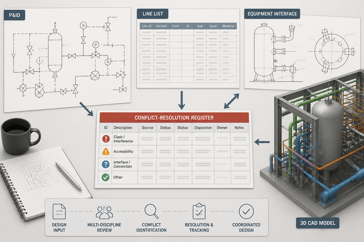
Resolving piping data conflicts before CAD modeling protects the design from errors that may be difficult to see in finished geometry. A line list, P&ID, equipment drawing, piping material specification, and layout document may each control a different part of the design.
This guide explains how to compare those sources, identify the right authority for each question, document temporary assumptions, and carry approved resolutions consistently into the CAD model.
Piping CAD errors often begin before anyone draws a line. A nominal size on the line list may differ from the P&ID. A nozzle orientation on an equipment drawing may not match the plot plan. A piping material specification may define an end connection that is inconsistent with the component shown in a preliminary model.
These are not merely drafting problems. They are information-control problems. If conflicting inputs are copied directly into CAD, the model can appear complete while containing disconnected, incompatible, or unverified design information.
A disciplined conflict-resolution workflow helps the designer identify which information is authoritative, record unresolved questions, and model only what is sufficiently defined. The goal is not to guess the correct answer. The goal is to make each design decision traceable.
Why piping information conflicts
Different project documents describe the same piping system from different viewpoints. A P&ID communicates process function and control intent. A line list organizes line attributes. A piping material specification defines permitted components and connections. Equipment drawings describe physical interfaces. A plot plan or layout drawing controls location and spatial relationships.
Because these documents develop at different times, they may not be synchronized. Common causes of conflict include:
- A process change updated the P&ID but not the line list.
- An equipment vendor revised a nozzle location after the piping layout was started.
- A piping specification changed, but old CAD blocks remained in the model.
- A preliminary line size was carried into a detailed drawing without confirmation.
- A revision cloud was removed from one document while related documents remained unchanged.
- Different teams used different naming conventions for the same service or connection.
Recognizing these causes helps prevent an important mistake: treating the first document found as the final authority.
Establish a document hierarchy before reviewing details
There is no universal order that makes every document authoritative for every question. Instead, assign authority by subject. The document that controls process flow may not control physical nozzle geometry, and the document that controls component selection may not control routing.

| Question | Usually reviewed first | CAD implication |
|---|---|---|
| What does the line do? | P&ID and process documentation | Confirm service, flow path, branches, valves, instruments, vents, and drains. |
| What attributes belong to the line? | Line list and approved process data | Check size, specification, insulation indication, and design basis fields. |
| Which components are permitted? | Piping material specification | Select compatible valves, fittings, flanges, gaskets, and specialty items. |
| Where does the line connect? | Approved equipment and interface drawings | Model nozzle location, orientation, elevation, and connection type from controlled information. |
| Where does the line run? | Layout, plot plan, structural, and access information | Coordinate routing, clearances, maintenance access, and support interfaces. |
This is a review framework, not a substitute for the project document-control procedure. If the project has an explicit precedence matrix, use that matrix and record exceptions.
Use a conflict register instead of informal corrections
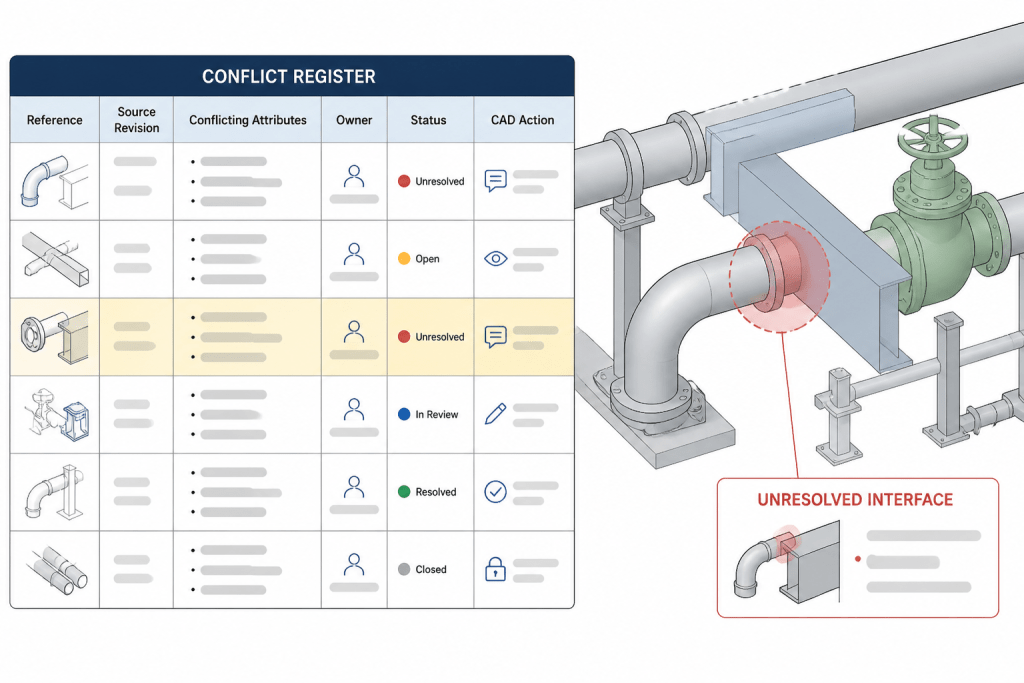
When two sources disagree, avoid silently changing one value to match another. Record the conflict in a simple register. The register may be a spreadsheet, database view, or issue-management record, provided that it identifies the affected item and its status.
- Reference: line number, equipment tag, branch, spool, or model object.
- Conflicting attributes: such as size, specification, routing point, nozzle orientation, or connection type.
- Source documents: document numbers, revision identifiers, and relevant locations.
- Current working value: the value temporarily used for coordination, if one is needed.
- Reason for the working value: for example, latest approved equipment interface or current process issue.
- Owner: the discipline or person responsible for resolving the question.
- Status: open, under review, resolved, superseded, or rejected.
- CAD action: model, hold, mark as provisional, or remove from the deliverable.
A conflict register separates verified information from temporary coordination assumptions. It also prevents the same question from being rediscovered during every drawing review.
Resolve conflicts in a practical sequence
1. Identify the affected system and boundary
Start with the smallest useful scope. Determine whether the conflict affects one component, one branch, a complete line, or an entire system. A mismatch at a pump nozzle may influence the first elbow, support arrangement, access envelope, and neighboring lines. A mismatch in a line attribute may affect material selection throughout the route.
2. Classify the information
Separate functional, dimensional, material, spatial, and document-control questions. This classification points toward the most relevant source. For example, use process documentation to investigate a missing branch function, but use an equipment interface drawing to investigate a nozzle location.
3. Check revision and approval status
Before comparing values, confirm that the documents are comparable. A superseded drawing can create a false conflict when compared with a current line list. Check revision identifiers, issue purpose, approval state, and whether the document was issued for information, review, construction, or another project stage.
4. Compare connected records, not isolated text
Review the complete chain around the discrepancy. For a line-size conflict, inspect connected equipment nozzles, reducers, valves, branches, and the material specification. For a route conflict, inspect the source and destination, elevations, structural constraints, access zones, and nearby lines. Local correction without system review can move the problem rather than solve it.
5. Select a controlled interim condition only when necessary
CAD coordination sometimes must continue while an issue is open. If so, clearly mark the condition as provisional and preserve the unresolved issue in the register. Do not present an assumed nozzle orientation, component type, or route as approved design information.
6. Apply the resolution consistently
Once the responsible discipline confirms the answer, update the affected model objects, drawings, schedules, and review records. Search for repeated instances of the old value. A resolved source document does not automatically correct copied CAD blocks, disconnected branches, or manually entered annotations.
CAD checks after a conflict is resolved
After updating the model, perform checks that focus on information continuity as well as geometry:
- Confirm that line identifiers remain consistent from the P&ID through the model and drawing.
- Verify that connected components have compatible end connections and belong to the intended piping specification.
- Check that revised equipment interfaces still align with the route and do not create an unreviewed offset.
- Review branch locations, valve positions, vents, drains, and instruments affected by the change.
- Confirm that annotations, tags, schedules, and material reports reflect the resolved data.
- Check whether supports, insulation, access, and maintenance clearances require a separate coordination review.
- Record the document revisions used for the final CAD update.
What not to do
Several shortcuts create unreliable reference data and difficult reviews:
- Do not choose the value that makes the geometry easiest to draw.
- Do not overwrite a source value without recording why it changed.
- Do not assume that a matching tag means every associated attribute is correct.
- Do not use a generic CAD block to conceal an unresolved connection or orientation.
- Do not close an issue merely because the drawing looks continuous.
- Do not treat a model export as proof that the underlying process, material, or equipment data is approved.
A reliable handoff from documents to CAD
The best time to find a piping data conflict is before detailed routing and annotation begin. A short document-reconciliation review can identify missing inputs, obsolete revisions, and authority gaps before they spread through the model.
Use a source matrix, maintain a conflict register, classify each question, and apply resolved information consistently across all affected objects. This approach makes CAD work more than a graphical transcription exercise. It creates a traceable connection between process intent, component selection, equipment interfaces, physical layout, and the final piping deliverable.
How to use this conflict-resolution method
The most useful principle is to treat a CAD model as the result of controlled engineering information, not as the place where conflicting information is decided. Before routing, determine what each source is intended to control and verify its revision and approval status.
Separate authority from convenience
A value should not become the working value simply because it produces cleaner geometry or is easier to find. If a temporary condition is required for coordination, identify it as provisional and preserve the open question in the project record.
Review interfaces as connected information
Many discrepancies affect more than the object where they are first noticed. A changed nozzle interface can influence adjacent routing, supports, access, and connected components. A changed line attribute can affect component selection and reporting throughout the route. Review the connected chain before closing the issue.
Make the final update traceable
After a conflict is resolved, update every affected model object, drawing, schedule, annotation, and review record. A visually continuous model is not enough; the associated identifiers, component data, document revisions, and interface conditions must also agree.
For drafting teams, this workflow provides a practical boundary between verified design information and coordination assumptions. For reviewers, it provides a clear way to see what was checked, who owns an unresolved question, and which CAD changes followed an approved decision.
Frequently Asked Questions
What is a piping data conflict?
A piping data conflict occurs when controlled project sources describe the same line, component, interface, or route differently. Examples include disagreement about line attributes, nozzle orientation, connection type, component selection, or physical routing.
Which document should control when piping documents disagree?
There is no universal authority for every question. Authority should be assigned by subject, such as process function, line attributes, component compatibility, equipment interfaces, or physical layout. If the project has a precedence matrix, follow it and record exceptions.
Should an unresolved conflict be modeled in CAD?
Only when coordination must continue and the condition can be clearly identified as provisional. The open issue should remain in the conflict register, and the model should not present an assumption as approved design information.
What information belongs in a conflict register?
Record the affected reference, conflicting attributes, source documents and revisions, any current working value, the reason for that value, the responsible owner, the issue status, and the required CAD action.
Why is revision status important during document comparison?
Documents from different project stages may appear to conflict even though one has been superseded. Comparing revision identifiers, issue purpose, and approval status helps distinguish a real discrepancy from a document-control problem.
What should be checked after a conflict is resolved?
Confirm continuity of line identifiers, compatibility of connected components, alignment at revised interfaces, affected branches and accessories, annotations, schedules, material reports, support and access implications, and the document revisions used for the CAD update.