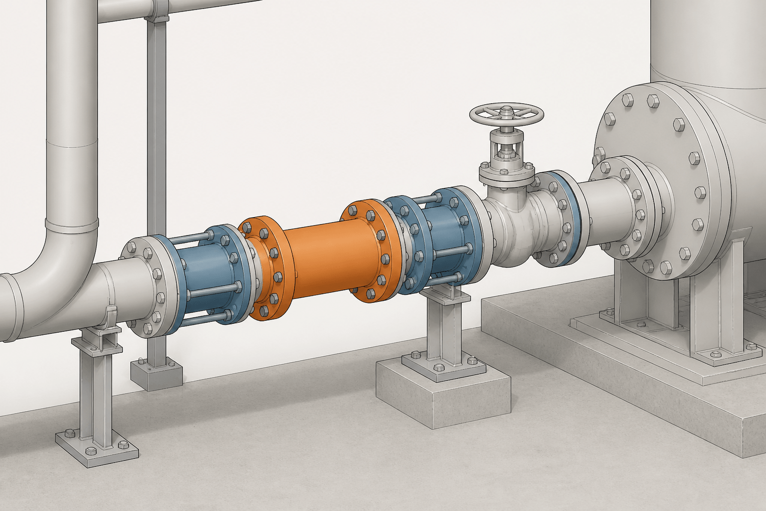
Removable spools and dismantling joints are not merely connection details. They communicate how piping can be assembled, separated, inspected, and maintained after installation. In a CAD model, the design intent must remain understandable across plan views, elevations, isometrics, schedules, and related project documents.
This guide explains the drafting decisions that make removal provisions visible and reviewable. It focuses on boundaries, component representation, access, support coordination, connection ownership, and document consistency without replacing the project specification or approved component information.
Removable pipe spools and dismantling joints are used to make piping easier to install, inspect, replace, or maintain. They are especially valuable around valves, pumps, strainers, meters, equipment nozzles, and other components that may eventually need removal. In a CAD model or drawing, however, their purpose is not always obvious. A line may appear continuous even though the design depends on a specific joint, flange pair, spool break, or separation point.
Good detailing makes the intended removal path visible without turning the drawing into a fabrication manual. The drafter must show where the piping can be separated, identify the relevant components, preserve the design intent, and coordinate the arrangement with supports, access, insulation, and adjacent disciplines.
What is a removable pipe spool?
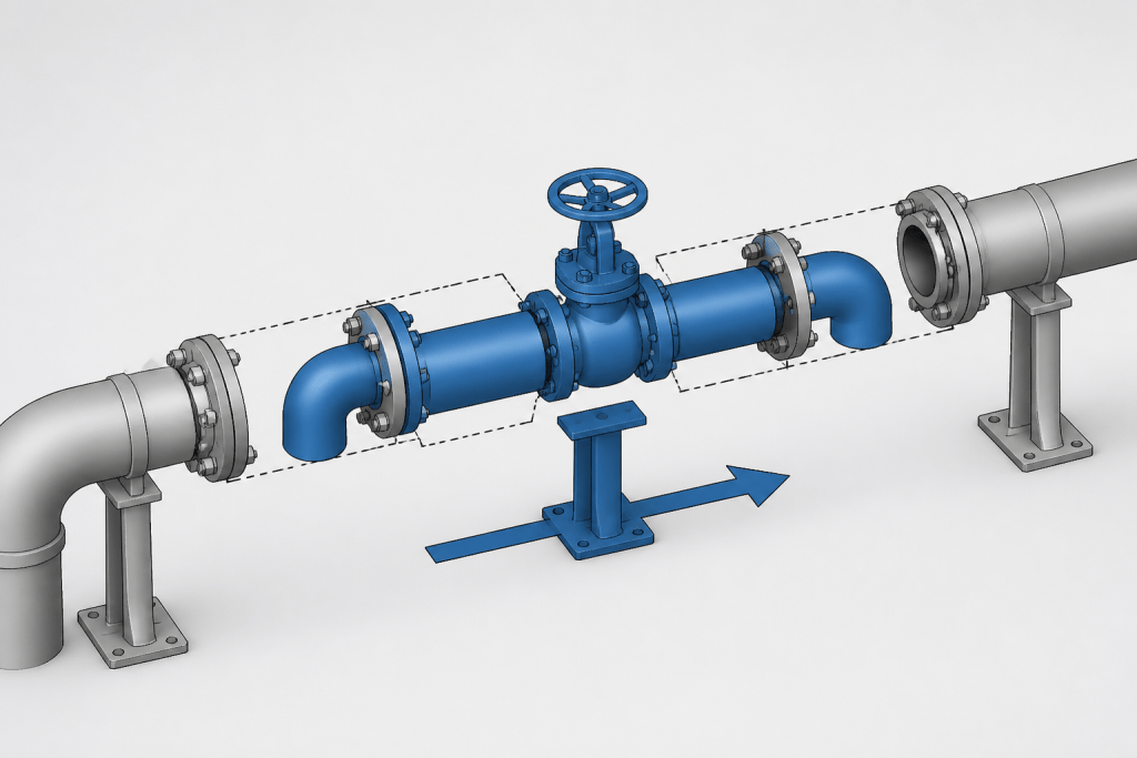
A removable spool is a prefabricated or field-assembled section of pipe and fittings that can be disconnected and removed as a unit. It may contain elbows, reducers, branches, valves, drains, vents, or instrument connections. The spool is normally bounded by joints that can be opened, such as flanged connections, mechanical couplings, threaded joints, or other project-approved connection types.
A spool break is the location where one piping assembly is separated from another for fabrication, transportation, erection, testing, operation, or maintenance. A spool break does not automatically mean that the connection is intended for frequent operation. It describes a practical division in the piping assembly and must be interpreted together with the drawing notes, material specification, and fabrication requirements.
What is a dismantling joint?
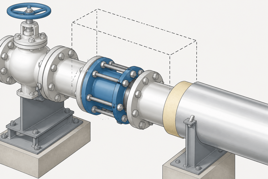
A dismantling joint is a mechanical connection designed to permit axial adjustment and disassembly of connected piping or equipment. It is often used near valves, pumps, meters, and other components that may need to be removed without cutting the pipe. The joint usually includes a restrained arrangement that allows the connection to be assembled or separated while accommodating the installation sequence defined by the project.
The exact configuration varies by manufacturer, service, material, and project requirements. For CAD purposes, the important issue is not to assume that every dismantling joint has the same geometry. Use the approved component representation, show the correct connection interfaces, and retain the manufacturer or project identification required by the design documents.
Why removal intent must be shown clearly
A piping drawing can be geometrically correct and still fail to communicate how a component is removed. This commonly happens when a valve is boxed tightly between elbows, when a flanged item has no visible separation space, or when a spool break is hidden by an annotation or dense linework.
Clear removal intent helps several groups:
- Designers: confirm that the arrangement supports the intended maintenance strategy.
- Fabricators: understand which items belong to a spool and where field connections occur.
- Construction teams: identify assembly sequence and access requirements.
- Operators and maintenance personnel: locate components that can be isolated and removed.
- Reviewers: verify that the piping model, bill of materials, and drawings describe the same arrangement.
Where removable arrangements are commonly used
Removal provisions are frequently considered at locations where a component is too large, too heavy, or too important to be permanently trapped in the line. Typical examples include:
- Valves installed between fixed pipe runs
- Pumps and other rotating equipment with flanged or removable connections
- Strainers, filters, and temporary commissioning equipment
- Inline meters and specialty instruments
- Expansion devices and flexible connectors
- Equipment nozzles where piping must be disconnected during maintenance
- Sections that may require internal inspection or replacement
This list describes common design considerations, not a universal requirement. Whether a removable connection is needed depends on the equipment arrangement, operating procedure, isolation philosophy, access strategy, and project specification.
CAD detailing workflow
1. Identify the item that may need removal
Start with the piping line, equipment connection, or component that drives the maintenance requirement. Confirm its tag, connection type, orientation, and relationship to nearby valves and supports. A removable arrangement should be based on the actual component geometry rather than a generic symbol alone.
2. Define the removal boundaries
Mark the joints or spool breaks that separate the removable item from the permanent piping. On an isometric drawing, this may involve showing flange symbols, connection identifiers, field weld indicators, or spool boundary marks. On a plan or elevation, use readable callouts and avoid placing the boundary where it is obscured by other graphics.
For a dismantling joint, show the joint as a distinct component rather than as an unexplained gap in the pipe. The drawing should make clear whether the joint is part of the line, part of an equipment connection, or supplied with another item.
3. Check the installation and removal path
Trace the physical path required to extract the component. Check nearby steel, platforms, walls, insulation, cable trays, equipment, and other piping. A component may be technically disconnected yet impossible to remove because the surrounding arrangement blocks vertical or horizontal movement.
Removal path reviews should consider the drawing view as well as the three-dimensional model. A plan may show adequate clearance in one direction while an elevation reveals an obstruction above or below the component.
4. Coordinate supports and restraints
Supports must not unintentionally prevent the spool or component from being separated. Review shoes, guides, line stops, anchors, spring supports, U-bolts, clamps, and temporary construction supports in the removal area. Also check whether disconnecting the joint would transfer unexpected weight to a nozzle, valve, or unsupported pipe segment.
Support coordination does not replace structural or piping flexibility review. The CAD check should identify arrangement conflicts and communicate the intended support relationship for the responsible engineering disciplines.
5. Confirm the connection and material requirements
Use the applicable piping material specification and approved component data to confirm the connection type, facing, gasket arrangement, bolting requirements, and material compatibility. Do not infer these details from the appearance of a symbol or from a similar component elsewhere in the model.
If the joint is supplied as part of a packaged item, identify the ownership boundary. This prevents duplicate procurement and clarifies whether the item belongs in the piping material takeoff, equipment package, or another bill of materials.
6. Add identification and notes
Use consistent tags for dismantling joints, flanged spool breaks, removable spools, and field connections. The note should explain the design intent without repeating information already available in the component schedule. Where necessary, reference the relevant spool number, line number, equipment tag, or maintenance note used by the project.
| Drawing element | Purpose | Common review question |
|---|---|---|
| Flange or mechanical joint symbol | Shows where the line can be separated | Is the connection type represented correctly? |
| Spool break or field connection | Defines fabrication or erection boundaries | Does the break match the spool drawing and model? |
| Component tag | Links the item to schedules and procurement data | Is the tag unique and consistent? |
| Removal or maintenance note | Communicates special intent | Can the component be removed without ambiguity? |
| Support representation | Shows how the assembly is held in place | Will supports obstruct separation or lifting? |
Common CAD mistakes
Showing a break without explaining it
A gap, line interruption, or flange-like graphic can be mistaken for a drafting error. Use the project symbol convention and add a clear identifier when the break has functional or fabrication significance.
Using a generic block for a special joint
A generic flange or coupling block may not represent the actual length, adjustment feature, or connection interfaces of a dismantling joint. Use approved geometry and verify the component data before issuing the drawing.
Ignoring insulation and access space
Insulation can hide bolts, covers, fasteners, or disconnection points. Show insulation breaks and removable sections where they affect access, and coordinate the arrangement with maintenance requirements.
Separating a component but not its attached items
Small-bore valves, vents, drains, instruments, and tubing may remain connected to the item being removed. Review all attached branches and decide whether they require flexible connections, additional breaks, or removal with the main assembly.
Failing to update related documents
A removable arrangement affects isometrics, spool drawings, material takeoffs, equipment layouts, support drawings, and sometimes maintenance documentation. After changing a spool break or joint, check every dependent deliverable rather than updating only the view where the change was made.
Final review checklist
- The removable component and its boundaries are identifiable.
- Connection types agree with the piping specification and approved component data.
- The removal path is clear in plan, elevation, and model views where applicable.
- Supports, guides, anchors, and restraints do not contradict the intended removal sequence.
- Insulation, access, lifting, and nearby obstructions have been reviewed.
- Attached small-bore piping and instruments have been considered.
- Tags, spool numbers, field connections, and material records are coordinated.
- Notes explain unusual intent without replacing detailed engineering requirements.
Removable spools and dismantling joints are small details with a large effect on constructability and maintenance. The strongest CAD deliverable does more than show a component in a line: it communicates how the component is connected, supported, accessed, and separated. When the drawing, model, schedules, and specifications all express the same removal strategy, review and field execution become much more predictable.
How to read removal intent in a piping drawing
Removal intent is easiest to understand when the drawing answers three connected questions: what must be removed, where it can be separated, and how it can be moved out of the installation. A flange, coupling, field connection, or dismantling joint may identify a separation point, but the surrounding arrangement determines whether that separation is useful in practice.
For this reason, review the connection together with adjacent elbows, branches, supports, insulation, platforms, equipment, and structural elements. A clearly drawn joint can still be ineffective if a support carries the removable section, an attached instrument remains connected, or nearby construction prevents the required movement.
Distinguishing fabrication breaks from maintenance provisions
Not every spool break is intended to support frequent maintenance, and not every visible flange represents a complete removal strategy. Fabrication and erection boundaries may exist for practical assembly reasons, while maintenance provisions are driven by access, isolation, component replacement, and operating procedures. The drawing notes, material specification, component data, and project conventions should establish how each connection is to be interpreted.
Maintaining this distinction helps prevent two common errors: treating a convenient fabrication break as a guaranteed maintenance feature, or omitting a deliberate removal provision because it resembles an ordinary connection. Consistent tags and notes should make the difference clear to designers, fabricators, construction personnel, and maintainers.
Model and drawing coordination priorities
- Use the approved representation for special joints and packaged components.
- Keep component tags, spool identifiers, connection ownership, and material records aligned.
- Check removal access in more than one view and in the three-dimensional model where available.
- Review small-bore branches, instruments, drains, vents, and tubing attached to the removable assembly.
- Recheck dependent drawings and schedules after changing a joint location or spool boundary.
The best deliverable makes the removal sequence understandable without overcrowding the drawing. Use geometry to show the physical arrangement, symbols to identify connection types, and concise notes to explain unusual intent or project-specific requirements.
Frequently asked questions
What is the difference between a removable spool and a dismantling joint?
A removable spool is a section of pipe and fittings that can be disconnected and taken out as an assembly. A dismantling joint is a mechanical connection intended to support separation and axial adjustment of connected piping or equipment. They may be used together, but they describe different aspects of the arrangement.
Does a spool break always indicate a maintenance connection?
No. A spool break may define a fabrication, transportation, erection, testing, or installation boundary. Its maintenance significance must be confirmed from the drawing notes, project requirements, material specification, and overall arrangement.
How should a dismantling joint be shown in CAD?
Show it as a distinct approved component with its correct connection interfaces and identification. Avoid representing it as an unexplained gap or substituting a generic block when the actual component geometry or ownership is important.
What should be checked around a removable component?
Check the separation points, extraction path, supports, restraints, insulation, access, nearby structures, attached small-bore piping, instruments, and equipment connections. Review plan, elevation, and model views because an obstruction may not be visible in every view.
Who needs clear removal intent on the drawing?
Designers, fabricators, construction teams, operators, maintenance personnel, and reviewers all rely on the information. Clear boundaries and coordinated identification help each group understand the intended assembly and maintenance strategy.