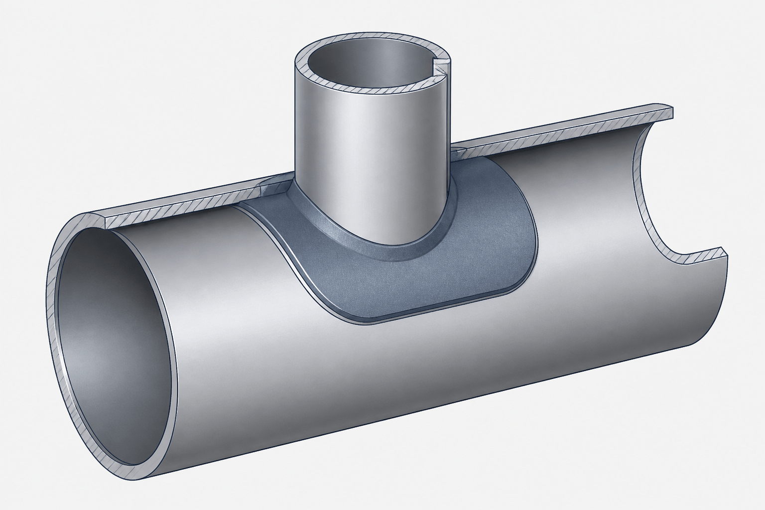
Pipe branch reinforcement pads are small CAD features with a large documentation impact. When the pad, saddle, or integrated reinforcement arrangement is unclear, the model can lose the connection between engineering approval, fabrication, inspection, and material control.
This guide provides a practical drafting and review workflow for representing approved branch reinforcement in piping models and drawings. It deliberately separates CAD communication from pressure-design decisions, so dimensions and configurations remain controlled by the responsible engineering documents.
Pipe branch reinforcement is easy to overlook in a crowded piping model. A branch connection may appear complete because the header, branch pipe, and fitting are shown, yet the design may also require a reinforcement pad, saddle, integrally reinforced fitting, or another engineered detail. If that information is missing from the CAD deliverable, fabrication, inspection, and material control can all become unclear.
This guide explains how to detail pipe branch reinforcement pads in CAD and how to review the associated information. It focuses on communication and model quality—not on selecting reinforcement sizes or approving a pressure design. The required reinforcement arrangement must come from the approved piping design, project specification, and responsible engineering review.
What a branch reinforcement pad does
A branch opening removes material from the run pipe. Depending on the branch size, geometry, loading, material, wall thickness, and design conditions, the opening may require additional reinforcement. A reinforcement pad is commonly a formed or flat ring-like plate fitted around the branch connection and welded to the run pipe or branch fitting.
The pad is not simply a decorative ring in the drawing. It can affect:
- the bill of materials and material takeoff;
- weld locations and inspection planning;
- clearance from nearby welds, supports, seams, and other fittings;
- insulation and coating details;
- drainage, venting, and corrosion-control provisions; and
- fabrication sequencing and access for welding.
Some branch connections use an integrally reinforced fitting instead of a separate pad. Others may use a contoured saddle or a locally engineered reinforcement arrangement. The CAD task is to represent the approved arrangement accurately and make its identity clear.
Information to confirm before modeling
Do not begin by drawing a generic reinforcement ring around every branch. First collect the design and drafting inputs that control the representation. The drawing package should establish whether reinforcement is required and what type has been approved.
| Input | Why it matters in CAD |
|---|---|
| Branch connection type | Determines whether the detail uses a pad, fitting, saddle, or another configuration. |
| Header and branch line identities | Connects the detail to the correct piping specification, material records, and isometric. |
| Approved reinforcement geometry | Controls the pad profile, opening, attachment arrangement, and section representation. |
| Weld and inspection requirements | Determines which welds and notes must be shown or referenced. |
| Nearby physical features | Helps reviewers identify interference with seams, supports, flanges, valves, or other branches. |
| Insulation, coating, and fireproofing information | Shows whether the pad affects the finished outside profile or requires a local treatment. |
If these inputs conflict, pause the modeling task and record the discrepancy. A visually convincing pad should not be used to conceal unresolved design data.
How to represent the pad in a piping model
Use a distinct component identity
Give the reinforcement pad its own component identity when the project data structure supports it. The item may require a separate catalog entry, material code, weld mapping, or fabrication note. Avoid burying the pad inside the branch pipe description unless the project’s material-control system explicitly treats it as part of that assembly.
A useful component record can distinguish the following:
- reinforcement pad or saddle designation;
- associated header and branch connection;
- material or material group;
- thickness or profile information from the approved design;
- fabrication status, such as shop-installed or field-installed; and
- related weld and inspection references.
Model the physical relationship, not just the outline
In a three-dimensional model, place the pad against the correct outside surface of the run pipe and align its opening with the branch connection. The model should make the relationship understandable when viewed from different directions. Check that the pad does not float away from the pipe, penetrate through the run wall unintentionally, or appear on the wrong side of the branch.
For a curved pad, use the approved contour rather than forcing a flat plate to follow a cylindrical surface. For a flat or segmented arrangement, show the intended geometry and any required breaks. The goal is not to add unnecessary modeling detail; it is to preserve the information that affects fabrication and review.
Drawing views that make the detail clear
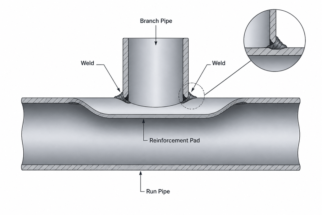
A plan or isometric view may identify the branch, but it often cannot explain the pad profile, weld boundaries, or relationship to the run-pipe wall. Add a dedicated detail or section when the general view is not unambiguous.
A useful branch reinforcement detail may include:
- a section through the branch centerline;
- the run pipe and branch wall outlines;
- the reinforcement pad profile and limits;
- the pad opening or clearance around the branch;
- the applicable weld symbols or weld references;
- orientation information for non-symmetrical pads; and
- notes directing the reader to the approved design or fabrication detail.
Use section hatching consistently so that the pad is not mistaken for a thickened pipe wall or an integral fitting. If the drawing uses a simplified symbol in the isometric, ensure that the detail view or component schedule provides the missing information.
Dimensioning and annotation strategy
Dimensions should allow the fabricator and reviewer to identify the part without forcing them to infer its shape from a crowded model. Show only controlled values that come from approved project data. Do not calculate or invent pad dimensions during drafting.
Depending on the approved detail, annotations may identify:
- pad thickness or material designation;
- inside and outside profile limits;
- branch opening relationship;
- orientation or clocking direction;
- edge preparation or fit-up information;
- weld references; and
- vent-hole or drain-hole provisions where specified by the design.
When a value is controlled by a separate calculation, standard detail, or engineering document, reference that controlling source through the project’s normal document-numbering method. A general note such as “per design” is useful only when the referenced design information is identifiable and available to the intended users.
Vent holes, drains, and corrosion considerations
Enclosed spaces between a pad and the run pipe can create fabrication, testing, coating, or corrosion concerns. Some designs include a small vent or drain provision; others use a different pad arrangement to avoid an enclosed pocket. The drafting team should not add or remove such a feature based on habit.
If a vent or drain is part of the approved arrangement, show its location, orientation, and identification clearly. Make sure it is visible in the relevant view and included in the material or fabrication documentation when required. If the project requires a hole to remain open during testing, coating, or service, that instruction should be stated through the appropriate design or fabrication note.
Common CAD review checks
Use a focused checklist rather than relying only on visual inspection:
- Identity: Is the reinforcement item associated with the correct header and branch?
- Location: Is it on the correct side of the run pipe and centered on the approved branch connection?
- Geometry: Does the modeled profile match the approved detail?
- Connectivity: Does the pad remain a reinforcement feature rather than being mistaken for a pipe or fitting?
- Welds: Are attachment welds represented or referenced consistently with the fabrication documentation?
- Clearance: Is there space for welding, inspection, insulation, coating, and nearby component operation?
- Material control: Does the item appear correctly in the component list or material takeoff?
- Views: Can a reviewer understand the arrangement without interpreting hidden geometry?
- Consistency: Do the model, isometric, detail drawing, and material records describe the same configuration?
Frequent detailing mistakes
Showing a generic ring without design control
A generic ring may look reasonable but can misrepresent the approved reinforcement geometry. Use it only as a temporary drafting placeholder, and make its status obvious until the design data is confirmed.
Counting the pad incorrectly
Omitting the pad from the material takeoff creates a procurement and fabrication problem. Counting it twice can create a different control problem. Decide whether the project treats the pad as an independent component or part of a fitting assembly, then apply that rule consistently.
Hiding the pad behind insulation
Insulation may conceal the physical feature in the finished model, but fabrication and inspection drawings still need the bare-pipe arrangement. Use separate display states, layers, or detail views where appropriate.
Adding a vent hole by drafting convention
Vent-hole requirements depend on the approved design and project practice. Do not add one automatically, and do not delete one to simplify the drawing.
Final drafting principle
A good branch reinforcement detail communicates three things at once: what the feature is, where it is installed, and which approved information controls its fabrication. CAD should make the engineered arrangement easier to build and review—not create an unverified design through assumed dimensions or familiar symbols.
Before issue, compare the model and drawing against the piping material records, branch connection detail, weld documentation, and current engineering approval. When those sources agree, reinforcement pads become traceable, reviewable components instead of ambiguous shapes around a branch connection.
How to use this guide during a CAD review
Review the branch reinforcement as a connected information set rather than as an isolated shape. The three-dimensional model should identify the physical relationship between the run pipe, branch, and reinforcement. The drawing should explain the profile, weld boundaries, orientation, and any required fabrication provisions. The component list and material records should identify how the item is controlled.
Separate design approval from drafting execution
CAD personnel commonly verify whether approved information has been represented consistently. They should not infer reinforcement requirements from appearance, branch size, drafting convention, or a similar connection elsewhere in the model. If the source documents do not establish the arrangement, the correct action is to record the gap and obtain clarification.
Trace the feature across project deliverables
A reliable review follows the pad through the documents that users will depend on:
- the piping model, where location and physical interference are checked;
- the isometric or fabrication drawing, where welds and detail references are communicated;
- the component list or material takeoff, where procurement and fabrication control are established;
- the engineering or standard detail, where the approved configuration is defined; and
- inspection and coating documentation, where access and treatment requirements may affect execution.
These records should describe the same arrangement. Differences in naming, status, geometry, or installation responsibility should be resolved before issue rather than left for fabrication or field interpretation.
Keep display states purposeful
Separate bare-pipe, fabrication, insulation, and review display states when the project workflow supports them. This allows reviewers to see the reinforcement without losing the finished-system context. A hidden or visually merged component is not necessarily absent from the design, but it becomes difficult to verify unless the drawing and component data expose it clearly.
Practical handoff principle
The strongest deliverable makes the reinforcement easy to identify without implying that the drafter selected its design. Show the approved geometry, provide traceable references, and make unresolved information visible. That approach supports clearer fabrication, inspection, procurement, and multidisciplinary review.
Frequently asked questions
Is a reinforcement pad required at every pipe branch?
No. The requirement depends on the approved piping design and the connection arrangement. Some branches use a separate pad, while others use an integrally reinforced fitting, saddle, or another engineered configuration.
Should the reinforcement pad be modeled as a separate CAD component?
It should have a distinct identity when the project data structure, material control, weld mapping, or fabrication workflow requires one. If the project treats it as part of an assembly, apply that rule consistently and make the relationship clear.
What should a branch reinforcement detail show?
The detail should communicate the run pipe, branch, reinforcement profile, attachment or weld references, orientation where needed, and any approved vent, drain, coating, or fabrication provisions. The controlling project information should be identifiable.
Can a drafter add a vent hole or drain based on common practice?
No. Such features should be shown only when they are part of the approved arrangement or are required by an identifiable project instruction. Drafting convention alone is not a design authorization.
How can reviewers find an omitted reinforcement pad?
Compare the branch connection detail, three-dimensional model, isometric, material records, weld documentation, and engineering approval. Look for mismatched component identities, unexplained geometry, missing takeoff items, and inconsistent display states.
Does insulation remove the need to document the pad?
No. Insulation may cover the feature in the finished-system view, but fabrication and inspection documentation still need to communicate the bare-pipe arrangement and related work requirements.