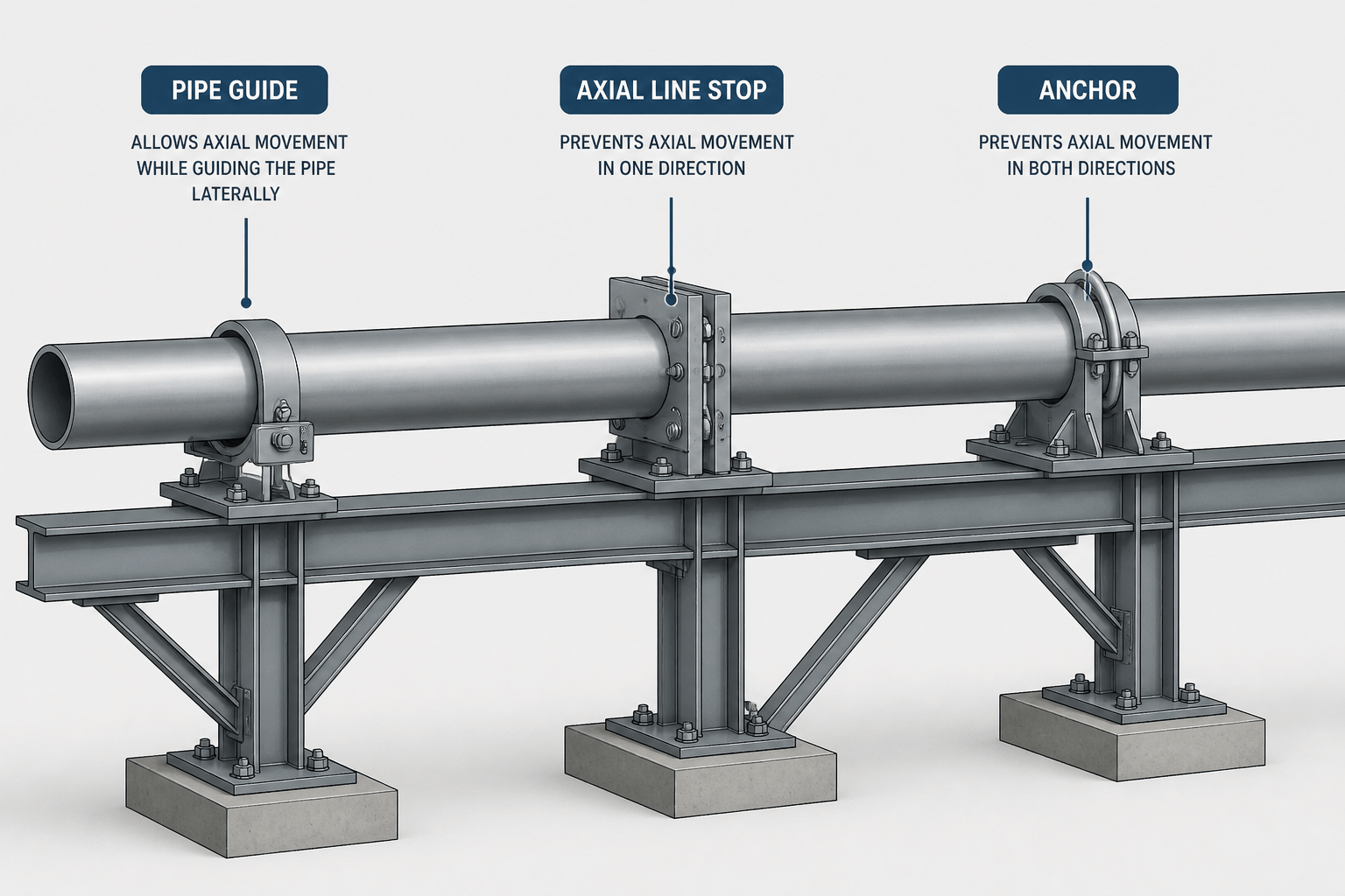
In piping CAD work, support terminology is part of the engineering intent. A symbol that appears to be a simple attachment may guide lateral movement, limit axial travel, or restrain the pipe and transfer reactions into the supporting structure.
This reference explains how to recognize those different functions and carry them consistently through models, drawings, support schedules, and coordination reviews. Use it alongside the project support philosophy, flexibility work, structural design, and approved support details.
Pipe guides, anchors, and line stops may look similar in a piping model, but they perform different control functions. Confusing them can create unclear support drawings, incorrect movement assumptions, and coordination problems between piping, structural, and mechanical teams.
This guide explains the terminology and provides a practical CAD workflow for identifying, modeling, documenting, and reviewing these supports. It does not replace a piping flexibility analysis, support design calculation, or project specification. The final arrangement must be checked against the applicable design basis and verified by the responsible engineering team.
Why the distinction matters
A piping support does more than hold a line in place. It can allow movement in selected directions, restrict movement in other directions, transfer loads into steel or concrete, or establish a deliberate reference point for a flexibility model.
The same physical support may include several functions. For example, a support assembly can carry vertical weight while also guiding the pipe laterally. A separate stop plate may limit axial travel without acting as a full anchor. CAD users therefore need to record the intended restraint behavior, not just draw a generic support symbol.
Pipe guide, anchor, and line stop compared
| Support type | Primary function | Typical movement behavior | CAD review focus |
|---|---|---|---|
| Pipe guide | Controls lateral movement while allowing selected axial movement | Usually permits movement along the pipe axis within the intended design arrangement | Guide clearance, orientation, attachment, and interference with insulation |
| Pipe anchor | Restricts pipe movement at a defined location and transfers reactions to the supporting structure | Intended to restrain multiple movement directions; exact behavior depends on the design | Anchor location, structural interface, load path, weld or clamp details, and analysis assumptions |
| Line stop | Limits axial travel in one or both directions | Allows some movement until the pipe contacts the stop surface | Stop orientation, travel direction, contact detail, and clearance before engagement |
These descriptions are functional rather than universal definitions. Company standards and support catalogs may use different names, and a project may define a line stop as a type of guide or restraint. Always compare the drawing symbol, support code, and design note with the project terminology.
How a pipe guide works
A guide is intended to keep a pipe on its planned route while allowing movement in a permitted direction. It commonly uses guide plates, structural steel members, clamps, or other components positioned around the pipe or shoe. The guide should control the movement that matters without unintentionally becoming an anchor.
In CAD, the most important information is the guide’s orientation relative to the pipe centerline. A guide that restricts movement across the line is not equivalent to one that restricts movement along the line. The plan view may show the lateral relationship clearly, while a section or elevation may be needed to show vertical clearance and the guide attachment.
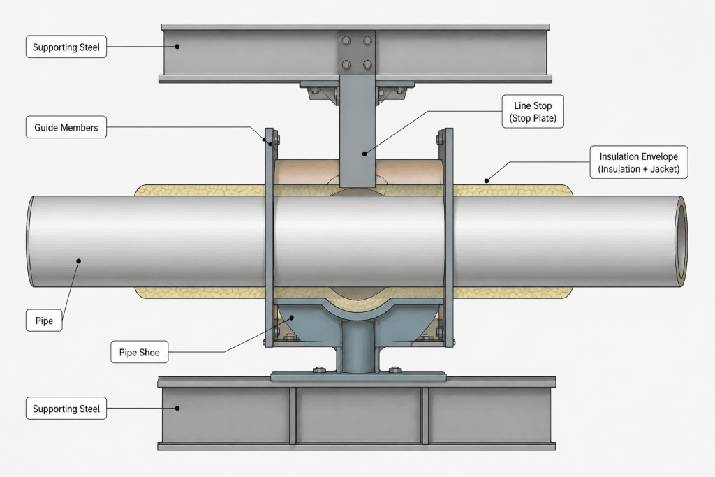
When insulated piping is involved, model and document the relevant outside envelope rather than relying only on the bare pipe representation. Check whether the guide contacts the shoe, insulation shield, or another component. A guide that appears correct around the nominal pipe line may be impractical if it conflicts with insulation, cladding, a removable cover, or a nearby weld.
How an anchor differs from a line stop
An anchor is a deliberate restraint point. It is normally associated with a defined load path from the pipe into a structural member, equipment connection, or engineered support assembly. Because an anchor can introduce significant forces, its location should be coordinated with flexibility analysis and structural design rather than selected only for drafting convenience.

A line stop is more limited. It prevents or limits axial travel when the pipe reaches a stop surface. Until contact occurs, the line may be free to move in the permitted direction. After contact, the stop can transmit a reaction. This contact-based behavior is important in analysis and should be represented consistently in the support model and the drawing notes.
Do not use the terms interchangeably in a support schedule. If the design requires a stop, label it as a stop and identify its permitted movement or engagement direction. If the design requires a fixed restraint, identify the anchor or restraint function and provide the appropriate support detail.
CAD workflow for detailing these supports
1. Start with the design intent
Before placing support geometry, review the line list, piping specification, flexibility deliverables, support philosophy, and equipment connection requirements available for the project. Identify whether the support is intended to guide, stop, anchor, or combine several functions.
Record the support identifier, pipe line reference, support elevation, structural attachment, and any movement direction stated by the design team. If the information conflicts, hold the CAD change and request clarification instead of resolving the restraint behavior by visual judgment.
2. Establish the pipe centerline and movement axes
Use the pipe centerline as the reference for the support location. In plan, determine the transverse direction. In elevation or section, determine the vertical relationship and available clearance. For sloping lines, make sure the support orientation follows the intended pipe axis rather than assuming that the sheet’s horizontal direction is the axial direction.
Show the coordinate or elevation information needed to relocate the support unambiguously. A support symbol without a clear relationship to the pipe, steel, or foundation can be difficult to fabricate and difficult to verify in the field.
3. Select the correct representation
Use the project’s approved support library where available. A guide, anchor, and line stop should not share an indistinguishable block unless a separate attribute, tag, or annotation identifies the function. Keep the graphical representation legible in plan, elevation, section, and isometric views.
For a detailed support drawing, show the important physical interfaces: pipe or shoe contact, guide members, stop plates, clamp components, base plates, welds or bolts where required by the project detail, and the supporting steel or concrete. Avoid adding fabrication information that has not been established by the responsible designer.
4. Coordinate with adjacent components
Review valves, flanges, branch connections, instruments, welds, insulation breaks, drains, vents, and removable items near the support. A support location that is acceptable in a centerline model may interfere with access or maintenance when the actual component envelope is considered.
Check structural framing as well. Guides and stops need a credible attachment point, while anchors may impose reactions that require a specific beam, column, frame, or foundation detail. If the supporting structure is not yet defined, use a clear coordination note rather than implying that an unverified member can accept the load.
What to show in drawings and schedules
- Support tag: Use one consistent identifier across the model, plan, isometric, support drawing, and schedule.
- Function: State whether the item is a guide, anchor, line stop, or combined support arrangement.
- Orientation: Describe the restrained or permitted direction when it is not obvious from the view.
- Elevation: Identify the support reference elevation using the project’s established convention.
- Attachment: Show or identify the supporting steel, concrete, equipment, or adjacent structural element.
- Clearance: Note guide or stop clearances when they are controlled design information.
- Special conditions: Identify insulation, sliding surfaces, corrosion protection, access requirements, or removable parts when applicable.
The schedule should support the drawing, not replace it. A support code may identify a standard arrangement, but the drawing still needs enough information to show orientation and interfaces clearly.
Common CAD errors
Using a generic support symbol
A generic symbol can hide the difference between vertical support, guide, stop, and anchor behavior. Use distinct symbols or attributes and make the legend explicit.
Ignoring direction
Placing a line stop without indicating which axial direction it controls leaves the design intent ambiguous. Add an arrow, note, or orientation convention approved for the project.
Modeling every restraint as fixed
This can produce an incorrect flexibility representation and an inaccurate understanding of thermal movement. Model the intended restraint behavior rather than assigning a fixed condition because it is convenient in CAD.
Failing to show the load path
A support that appears to float, terminate in insulation, or attach to an unrelated member is not complete. Trace the physical path from pipe to support hardware to structure and flag missing interfaces.
Overlooking installation and maintenance
Guides and stops may require clearance for installation, inspection, insulation work, or replacement. Review access and removal paths in addition to geometric clearance.
Final review checklist
- Does the support function match the design documentation?
- Is the pipe axis and restraint direction clear in the selected views?
- Are guide clearances and stop contact conditions represented consistently?
- Does the support connect to a defined structural or equipment interface?
- Are insulation, shoes, clamps, welds, and removable components coordinated?
- Do support tags and descriptions agree across all deliverables?
- Has the arrangement been reviewed against flexibility and structural requirements?
Clear support detailing begins with clear terminology. Treat guides, anchors, and line stops as different restraint functions, document their intended movement behavior, and coordinate every support with its physical load path. That approach makes CAD drawings easier to review and reduces the chance that a visual symbol will be mistaken for an engineering decision.
Reading support behavior from a CAD model
The most reliable way to review a support is to ask what movement it permits, what movement it restrains, and where the resulting load travels. Geometry alone may not answer those questions. A guide, stop, or anchor can be represented by similar plates, clamps, shoes, or steel members while having different design behavior.
Separate geometry from function
When reviewing a model, first identify the pipe axis and the relevant transverse and vertical directions. Then compare the visible hardware with the support tag, schedule description, design note, and analysis assumptions. If these sources do not agree, the discrepancy should be resolved by the responsible engineering team rather than inferred from the drawing.
Use views that explain the restraint
Plan views are often useful for showing lateral guide relationships, while sections and elevations can clarify vertical clearance, stop contact, insulation envelopes, and structural attachments. Isometric views help trace the physical load path, but they should not be expected to communicate every movement condition by themselves.
Review contact and engagement conditions
Some support behavior depends on contact that occurs only after movement. For these arrangements, distinguish the free condition from the engaged condition and document the intended direction of travel. This is especially important when a line stop or guide could be mistaken for a continuously fixed restraint.
Practical review questions
- What is the support intended to control: lateral movement, axial travel, several movement directions, or a combination?
- Is the support orientation understandable without relying on an undocumented drafting convention?
- Does the modeled envelope account for insulation, shoes, clamps, access, and removable components?
- Can the load path be followed from the pipe through the support hardware to steel, concrete, equipment, or another defined interface?
- Do the model, drawing, schedule, and flexibility assumptions describe the same restraint behavior?
These questions help CAD and coordination teams identify ambiguous detailing early. They do not establish a support design or replace the calculations and approvals required by the project.
Frequently Asked Questions
What is the main difference between a pipe guide and a line stop?
A pipe guide primarily controls movement across the pipe route while allowing selected axial movement. A line stop limits axial travel when the pipe reaches its stop surface. The project terminology and support detail should control when a combined arrangement is used.
Is a pipe anchor the same as a fixed support?
Not necessarily. An anchor is a deliberate restraint point with a defined load path and intended movement restrictions, but the exact behavior depends on the engineered arrangement. Do not assign a fixed condition merely because the CAD symbol appears rigid.
Why should insulation be considered when detailing a guide?
Insulation, cladding, shields, and removable covers can change the physical envelope around the pipe. The guide must be checked against the component it is intended to contact and against the clearance needed for installation, inspection, and maintenance.
How should a line stop be shown in a CAD drawing?
Show the stop orientation, the controlled axial direction, the contact detail, and the clearance before engagement when those are controlled design requirements. The support tag and schedule should use the same function name.
What should be done when the support symbol and schedule disagree?
Hold the change and request clarification from the responsible engineering team. A CAD user should not resolve conflicting restraint behavior by visual judgment because the difference can affect flexibility assumptions, structural reactions, and coordination.