
Pipe elevation notes are only reliable when the drawing identifies the exact physical reference behind the label. In CAD coordination, “elevation” may describe an axis, an outside surface, an insulated envelope, an internal flow surface, or a connection face.
This guide provides a practical framework for reading and creating pipe elevation callouts. Use it alongside the project datum, approved piping geometry, equipment information, and drafting conventions so that the drawing communicates the intended physical location without ambiguity.
Pipe elevation dimensions are only useful when everyone understands what part of the pipe the dimension references. A routing note that says “elevation” may refer to the pipe centerline, bottom of pipe, top of pipe, invert, or even the face of a connected component. If those references are mixed, a drawing can appear coordinated while placing the physical pipe at the wrong height.
This guide explains common pipe elevation terminology and presents a practical CAD workflow for selecting, labeling, and checking elevation references. It is intended for drafting and coordination. Project specifications, equipment requirements, process criteria, and the applicable design basis still control which reference should be used.
Why elevation reference matters
A pipe can be represented by a single line in a plan view, but the real pipe has outside diameter, wall thickness, insulation, supports, and connection geometry. A dimension to the centerline does not communicate the same physical location as a dimension to the bottom or top of the pipe.
The distinction becomes important when piping is coordinated with:
- Structural steel, platforms, floors, and pipe racks
- Equipment nozzles and connection points
- Drains, trenches, channels, and buried services
- Insulation, heat tracing, cladding, and removable covers
- Pipe supports, shoes, guides, and anchor locations
- Other piping systems crossing above or below the route
Using a consistent reference helps reviewers compare the drawing with the model, equipment data, support details, and field conditions. The first step is to identify what the elevation callout actually represents.
Common pipe elevation references
| Reference | Meaning | Typical coordination use |
|---|---|---|
| Centerline elevation | Elevation of the pipe axis | General routing, isometrics, and alignment between connected components |
| Bottom of pipe | Lowest outside surface of the bare pipe | Clearance below the pipe and support or structural coordination |
| Top of pipe | Highest outside surface of the bare pipe | Overhead clearance and vertical congestion checks |
| Bottom of insulation | Lowest outside surface of the insulated assembly | Clearance, access, and support-interface reviews |
| Top of insulation | Highest outside surface of the insulated assembly | Clearance above the finished piping assembly |
| Invert elevation | Lowest inside flow surface of a pipe or channel | Gravity-flow systems and drainage coordination |
| Flange-face elevation | Elevation of the gasket-contacting face of a flange | Equipment and flanged connection alignment |
The exact meaning of an abbreviation varies between projects, so the drawing legend or project drafting standard should define terms such as CL, BOP, TOP, BOI, TOI, and INV before they are used extensively.
Centerline elevation
The centerline is the axis running through the pipe. For a straight horizontal pipe, its elevation is easy to represent in a section or isometric. For a vertical pipe, the centerline may be shown by a plan location and a series of elevations along the route.
Centerline elevations are common because they provide a stable geometric reference. The pipe diameter does not change the axis location, so connected runs can be aligned without repeatedly dimensioning the outside surface. This is especially useful for piping layouts, isometric coordinates, and connections between standard components.
However, a centerline elevation does not directly show the available space above or below the pipe. A reviewer who needs to verify a platform clearance or overhead obstruction must also know the pipe outside diameter and any relevant insulation thickness.
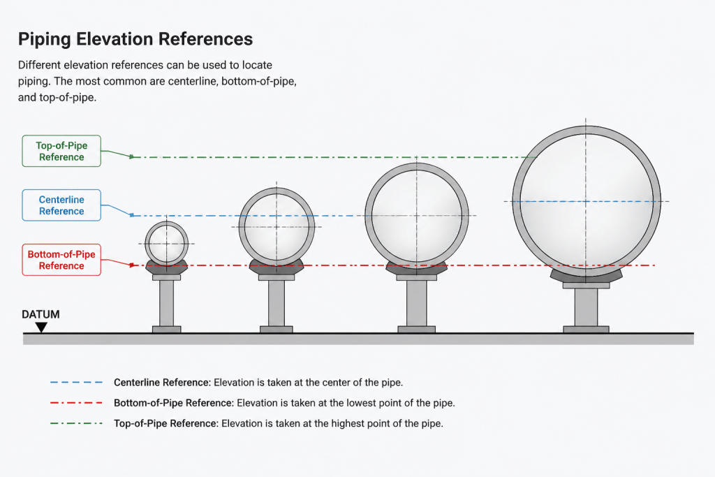
Bottom-of-pipe and top-of-pipe references
Bottom-of-pipe, commonly abbreviated BOP, identifies the lowest outside surface of the bare pipe. Top-of-pipe, or TOP, identifies the highest outside surface. For a level run, these references can be related to the centerline using the pipe’s outside diameter from the project’s approved dimensional data.
BOP is useful when the lower surface controls a clearance, support interface, or trench relationship. TOP is useful when the upper surface controls access space, a rack elevation, or an obstruction check. Neither reference should be assumed to include insulation unless the callout explicitly says so.
When insulation is present, distinguish the pipe surface from the finished insulated envelope. A dimension marked BOP may stop at the pipe wall, while a clearance requirement may depend on the bottom of insulation. Showing both references can prevent a common coordination error: a route that clears structural steel as bare pipe but conflicts after insulation is added.
Invert elevation
Invert refers to the lowest inside surface of a pipe, channel, or similar passage. It is primarily useful where gravity and internal flow level matter. Invert is not interchangeable with BOP: BOP describes the outside surface, while invert describes the inside flow surface.
The difference depends on the pipe wall and lining arrangement. For a lined or internally coated system, the relationship may also involve the lining thickness. Use the project’s approved geometry and terminology when converting between internal and external references.
In CAD, an invert callout should be placed where its reference is unambiguous. A leader, section marker, or detail can show whether the dimension terminates at the inside bottom surface rather than at the outside of the pipe. This is particularly important where multiple pipes have similar centerline elevations but different diameters.
Flange-face and connection elevations
A flanged connection may require more than a pipe centerline dimension. The flange face is the contact surface where the gasketed joint is made. Its location can matter when coordinating an equipment nozzle, removable spool, valve assembly, or bolt-up space.
For a horizontal flange, the face may be located by a plan or longitudinal dimension. For a vertical flange, its elevation may be combined with a centerline or nozzle orientation reference. Do not infer the flange-face location solely from a pipe axis if the component has a special end-to-face dimension, an offset, or a nonstandard orientation.
Connection drawings should identify the reference used for the mating point. A pipe centerline can align while the flange face remains incorrectly positioned, especially when fittings, valves, reducers, or equipment necks are represented with simplified CAD blocks.
A practical CAD workflow
1. Establish the project datum
Confirm the elevation datum before placing the first route. The datum may be a finished floor, structural reference, equipment foundation, site benchmark, or another project-defined plane. Keep the datum name visible in the drawing notes or coordinate system documentation.

2. Identify the controlling reference
Decide whether each major route is controlled by centerline, BOP, TOP, invert, flange face, or a combination. Base the decision on the coordination need rather than on a habit from another project.
3. Set the primary routing geometry
Place the pipe centerline or connection point using the approved coordinates and equipment information. Use consistent CAD layers, object properties, or model parameters so the reference can be queried later.
4. Derive physical surfaces
Show or calculate the relevant outside surfaces from the pipe dimensions in the project database. Add insulation or lining envelopes when they affect clearance. Avoid manually typing derived values in multiple locations, because independent edits can create conflicting elevations.
5. Annotate the drawing explicitly
Use labels such as “CL EL,” “BOP EL,” “TOP EL,” “INV EL,” or “FLANGE FACE EL” only when the project convention defines them. Place the annotation close enough to the route to remove ambiguity, but not so close that it reads as a dimension to an adjacent line.
6. Check connected references
At every equipment or piping connection, compare the drawing reference with the source information. Check the nozzle centerline, flange face, orientation, and connection direction. A pipe may have the correct centerline elevation but still miss the required face-to-face location.
7. Review the finished envelope
Perform a separate check for bare pipe, insulation, supports, and nearby structures. Review both the upper and lower clearances. A route that is correct by centerline can still be unsuitable for the surrounding arrangement if the physical envelope is not considered.
Common drafting mistakes
- Using “elevation” without identifying the reference surface
- Mixing centerline and BOP dimensions on the same view without labels
- Treating BOP as the bottom of insulation
- Using invert and BOP as if they were the same location
- Dimensioning to a simplified block instead of the actual connection face
- Copying an elevation from a nearby route without checking diameter or insulation
- Failing to update derived elevations after changing pipe size or insulation
- Showing a slope with only one elevation and no clear reference points
Final review checklist
Before issuing a piping plan, section, or isometric, confirm that each important elevation answers three questions: what point is being dimensioned, what datum is being used, and whether the dimension describes bare pipe, insulated pipe, or an internal flow surface. Then verify the same reference at connections, supports, crossings, and equipment interfaces.
Clear elevation terminology does not replace engineering analysis or project requirements. It gives the design and drafting team a shared geometric language, making the authoritative dimensions, models, and coordination checks easier to interpret and less likely to be misapplied.
How to read a pipe elevation callout
When reviewing a plan, section, or isometric, first locate the dimension text and its leader or extension lines. Then determine the referenced point, the datum from which the elevation is measured, and whether the reference describes bare pipe, insulation, lining, or a connected component.
This distinction is especially important when a drawing uses a simplified single-line representation. The line may represent the pipe axis rather than an outside surface, while nearby structural, access, or maintenance requirements depend on the physical envelope. A clear annotation makes that interpretation explicit.
Why consistent terminology improves CAD coordination
Consistent elevation terminology helps different disciplines compare drawings, models, equipment documents, and field conditions. It also reduces the risk of treating a derived surface as an independently controlled dimension. When a route changes, the drawing team can identify which elevations should update from the approved geometry and which references remain controlled by a connection or project datum.
For practical review, inspect elevation references at route changes, supports, crossings, insulated sections, gravity-flow connections, and equipment interfaces. These locations often reveal whether the selected reference matches the actual coordination requirement.
Frequently asked questions
Is pipe elevation usually the centerline?
Not necessarily. Centerline is common for routing and alignment, but a project may control a route using bottom of pipe, top of pipe, invert, insulation surfaces, or a connection face. The drawing abbreviation and project convention should identify the intended reference.
Are BOP and bottom of insulation the same?
No. BOP refers to the lowest outside surface of the bare pipe. Bottom of insulation refers to the finished insulated assembly. They should not be treated as interchangeable during clearance or support reviews.
How is invert different from BOP?
Invert identifies the lowest inside flow surface, while BOP identifies the lowest outside surface of the bare pipe. Wall, lining, or coating geometry can affect the relationship between them.
When is a flange-face elevation needed?
A flange-face reference is useful when the mating location, gasket contact surface, equipment nozzle, valve assembly, or bolt-up arrangement controls coordination. Pipe centerline alignment alone may not establish the correct face position.
What should an elevation note include?
A useful note identifies the reference point or surface, the project datum, and the condition being described, such as bare pipe, insulated assembly, internal flow surface, or flange face. The applicable drawing legend should define the abbreviation.
Why can a correct centerline still produce a coordination problem?
A centerline controls the pipe axis but does not by itself show the upper and lower physical envelope, insulation, supports, or connection face. Those elements must be checked separately when they affect clearance or fit-up.