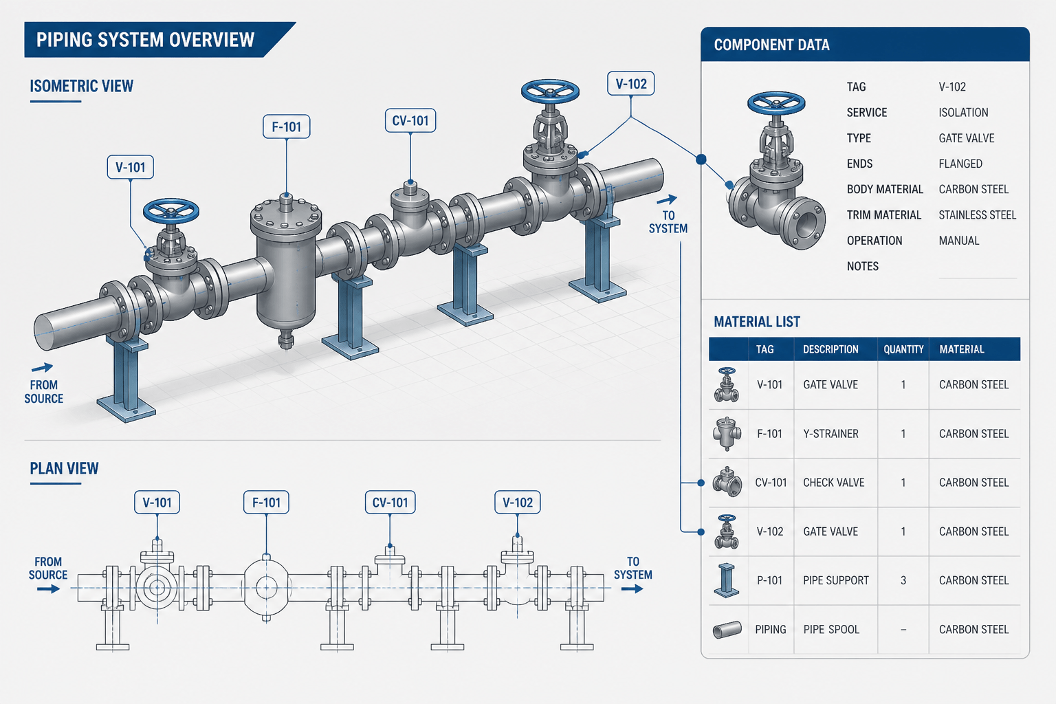
Reliable piping documentation depends on more than readable symbols. Component tags must remain connected to the model object, drawing callout, line relationship, and reporting data throughout design changes. When those links are controlled, reviewers can trace an item quickly and identify discrepancies before they affect procurement, construction, or maintenance records.
This reference explains how to organize piping component identity in CAD while leaving the project’s naming convention and data requirements under the control of the owner, engineering contractor, or document-control system.
Piping component tagging in CAD is more than placing a valve number or equipment identifier beside a symbol. A reliable tagging method connects the model, drawing annotations, material takeoff, line list, and review process. When those connections are weak, a drawing may look complete while still containing duplicate tags, missing components, or callouts that do not match the bill of materials.
This guide explains a practical way to structure and check piping component tags without replacing project-specific naming rules. The exact tag format should come from the project data environment, piping material specification, plant convention, or owner requirements. The objective is to make every component identifiable, traceable, and easy to verify.
What a piping component tag is supposed to do
A component tag is an identifier assigned to a valve, specialty item, inline instrument, strainer, sight glass, flexible connector, or other identifiable piping item. Depending on the project, the tag may be shown in the model, on an isometric, in a plan or elevation, in a piping and instrumentation diagram, and in procurement or maintenance records.
A useful tag should answer a basic question: “Which exact component does this note, record, or review comment refer to?” It should not be confused with the component description, nominal size, pressure class, material code, or line number. Those attributes may appear near the tag, but they serve different purposes.
| Information | Purpose | Typical CAD use |
|---|---|---|
| Component tag | Identifies one specific item | Callout, model property, inspection reference |
| Line number | Identifies a piping system or line segment | Line label, isometric title data, process reference |
| Component description | Explains what the item is | Drawing note, schedule, material takeoff |
| Specification or material code | Defines the approved component family or material requirements | Model property, selection, procurement data |
| Service or function | Explains operational purpose | Review note, P&ID relationship, operating record |
Separate identity from description
One of the most common tagging errors is using a descriptive phrase as though it were a unique identifier. For example, “block valve” describes a function or component type, but it does not identify one particular valve in a facility. Several valves may have the same description while each has a different tag.
CAD data should therefore distinguish between an identifier field and descriptive fields. A component may have properties for tag, type, size, rating, material, end connection, operator, insulation status, and remarks. The tag should remain stable even if the description is refined during design development.
This separation also helps when a component changes type. If a project-approved valve arrangement changes during engineering, the component description or specification may change while the item remains associated with the same approved tag. Whether a tag may be reused, retired, or reassigned must follow the project revision and document-control process.
Use a consistent tagging structure
Before placing tags in drawings, define the information structure that the CAD system will use. The structure should be simple enough for designers to apply consistently and detailed enough for reviewers to identify missing data.
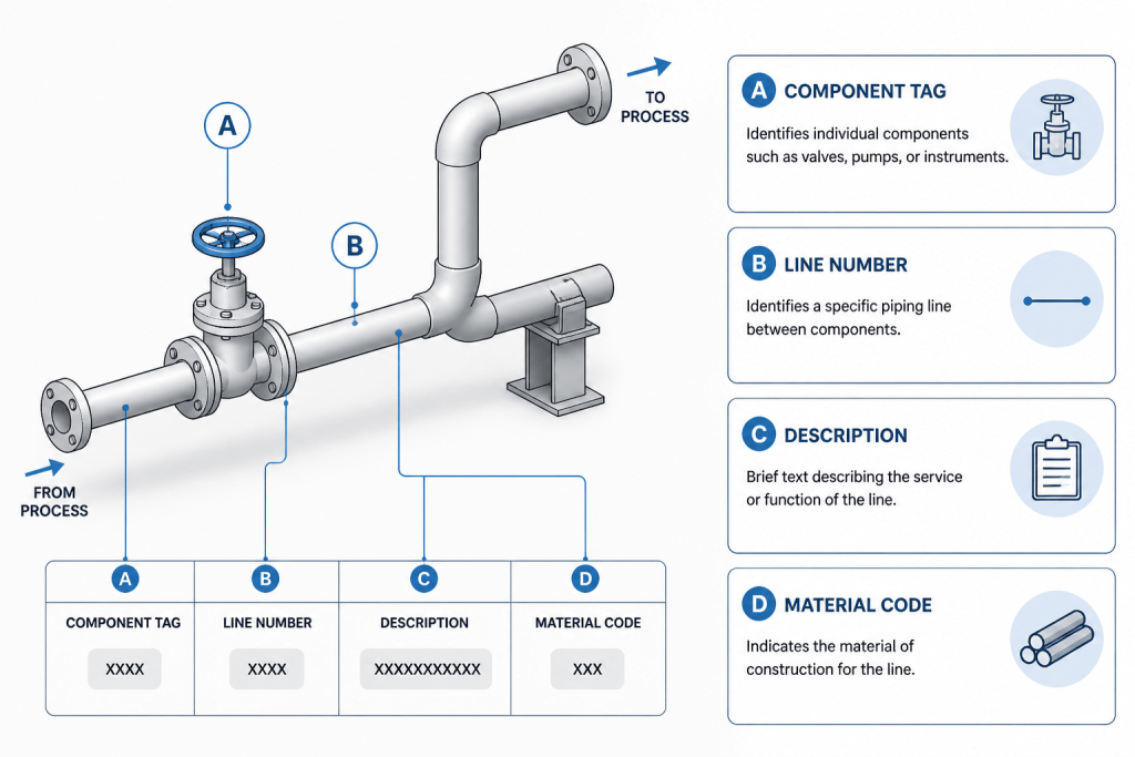
At a minimum, establish the following rules:
- Which component categories require individual tags.
- Which items are identified only by line number or material takeoff.
- Whether tags are assigned by discipline, area, system, equipment group, or another project convention.
- Which characters are permitted and which separators are reserved.
- How temporary, spare, future, demolition, and existing items are distinguished.
- How tag changes are recorded during revisions.
- Which drawing views must display the tag.
Do not create a local tagging format in a single drawing just because it appears convenient. A format that is understandable to one designer can become confusing when drawings are combined into a project set or exported to another database.
Assign tags at the right point in the workflow
Tagging too early can create unnecessary rework, but tagging too late can hide missing components. A practical workflow assigns preliminary identity during model creation and confirms the final tag during a coordinated data review.
During routing and component placement
When a component is added to the model, populate its required identity and classification fields rather than leaving a generic placeholder. Confirm that the selected catalog item belongs to the intended piping specification and that the component is connected to the correct line or branch.
During model coordination
Check that the component has not been copied unintentionally, replaced without updating its properties, or disconnected during a routing change. A visible symbol is not enough; the model object must carry the correct data.
During drawing extraction
Generate callouts from component properties where the CAD platform supports data-driven annotations. Manually typed tags can be appropriate in controlled situations, but they require an additional comparison against the model or equipment register.
Before issue
Run a tag audit across the model, drawings, schedules, and material reports. Treat the audit as a data check, not only a graphical check.
Place callouts for readability and traceability
A tag is useful only if a reader can tell which component it belongs to. Place the callout near the component without obscuring the symbol, flow direction, weld information, dimensions, or access notes. Use a leader when proximity alone could create ambiguity.
On congested isometrics, avoid stacking several leaders into one area. Arrange callouts so that each leader terminates clearly at the intended component. If a leader crosses another line, dimension, or annotation, adjust the layout instead of relying on guesswork.
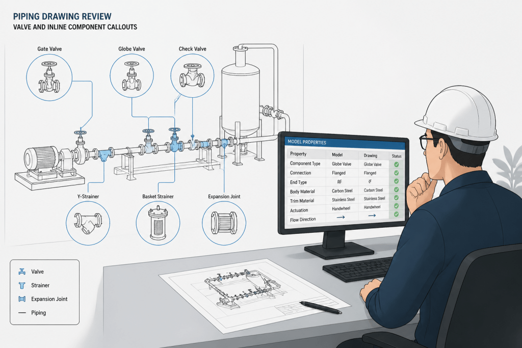
Repeated views require special attention. A component may appear in a plan, elevation, section, and isometric. The displayed tag should identify the same object in every view. If a drawing uses abbreviated callouts, the abbreviation should remain unambiguous and should be explained by the project’s annotation convention.
Keep tags synchronized with the bill of materials
A material takeoff may group similar components by type, size, or specification, while the drawing uses individual tags. These are different reporting needs, but they must still agree on component count and identity.
Check the following relationships:
- Every tagged component in the model appears in the appropriate material or component report.
- Every tag shown on an issued drawing exists in the model or approved source register.
- No two active components share a tag unless the project convention explicitly allows grouped identification.
- Removed or superseded components are not still reported as current items.
- Component descriptions and specifications match the selected catalog or project data.
- Items shown as existing, demolished, temporary, or future are classified consistently across documents.
When a report is generated from model data, investigate unexpected quantities before editing the report manually. A quantity difference may indicate a duplicate object, a missing connection, an incorrect component class, or a filtering error.
Common tagging failures and better controls
| Failure | Why it causes problems | Useful control |
|---|---|---|
| Duplicate tag | Reviews and maintenance records may refer to different items using the same identity | Run a uniqueness check across the active model |
| Unassigned tag | A component cannot be traced from the drawing to the model or register | Filter for blank identity fields before extraction |
| Manual callout not updated | The drawing displays obsolete information after a model change | Compare annotations with model properties after revisions |
| Tag attached to the wrong object | Fabrication, inspection, or review comments may target the wrong component | Check leader endpoints and object selection in each view |
| Inconsistent existing or future status | Construction and demolition scope becomes unclear | Use controlled status properties and drawing filters |
| Overloaded tag format | Long identifiers reduce drawing readability and increase entry errors | Keep identity separate from descriptive attributes |
A practical CAD review checklist
Before issuing a tagged piping drawing, review the data in a repeatable sequence:
- Confirm that each required component category has an assigned identity.
- Search for duplicate, blank, placeholder, and invalid tags.
- Compare model tags with callouts in every issued drawing view.
- Verify that leaders point to the intended components.
- Compare component counts and descriptions with the material or component report.
- Check line associations, specification assignments, and status classifications.
- Review recent changes for tags affected by relocation, replacement, deletion, or line rerouting.
- Record unresolved exceptions instead of silently correcting them in the drawing.
Why disciplined tagging improves piping documentation
Consistent component tagging reduces more than drawing clutter. It improves model navigation, supports material control, makes review comments precise, and helps connect design information with construction and maintenance records. It also provides an early warning when a model contains disconnected or poorly classified objects.
The most reliable approach is to treat a tag as controlled project data, not as decorative text. Define the rules, assign identity through the model or approved register, generate annotations consistently, and compare every issued view and report. That workflow keeps piping drawings readable while preserving the traceability that engineering teams need.
How to think about tagging as engineering data
The most useful mental model is to treat a tag as a controlled data key rather than ordinary annotation text. The key points to an identifiable component, while related properties explain what that component is, where it belongs, and how it should be handled. This distinction makes it easier to update drawings without losing traceability.
Model data is the source relationship
A callout is only a representation of the component identity. The model or approved register should remain the authoritative relationship whenever the project workflow supports it. If a designer changes a component location, replaces a catalog item, or revises a line association, the identity and related properties should be reviewed together.
Reports are another view of the same data
A bill of materials, component schedule, and line list may present information differently, but they should not create competing identities. Differences in grouping or description can be acceptable when they follow the reporting purpose. Differences in component count, status, or active tag require investigation.
Use exceptions instead of hidden corrections
When a tag, callout, or report does not agree with the model, record the discrepancy and resolve its cause. Quietly editing a drawing annotation or manually changing an exported report can conceal the underlying data problem and allow it to return in a later issue.
Questions to ask during a tagging review
- Can a reviewer select the component in the model and find the same identity in the drawing?
- Can the drawing tag be traced to the correct component record without relying on visual proximity alone?
- Are status, line association, classification, and specification properties populated consistently?
- Will a model revision update every dependent annotation and report, or is a manual comparison required?
- Are unresolved differences documented with an owner and a resolution path?
Frequently asked questions
Should every piping component receive an individual tag?
Not necessarily. The project convention should define which components require individual identification and which may be represented through a line number, material report, or another controlled reference. The important requirement is that the rule is documented and applied consistently.
Is a component tag the same as a line number?
No. A component tag identifies a particular item, while a line number identifies a piping system or line segment. They may appear together, but they support different tracing and review tasks.
Can a tag be typed manually in a CAD drawing?
Manual callouts may be used where the project workflow permits them, but they need a comparison against the model or approved register. Data-driven annotations reduce the risk of leaving obsolete text after a design change.
What should be done when a component is replaced?
Review the project’s revision and document-control rules before retaining, retiring, or reassigning the identity. Update the component properties, affected views, and reports together, and document any exception that cannot be resolved immediately.
Why can a BOM quantity disagree with the drawing?
A difference may result from a duplicate object, missing component, incorrect classification, disconnected branch, status filter, or reporting rule. Investigate the model and report logic before changing the exported quantity by hand.
How can crowded isometric drawings remain readable?
Keep callouts close to their components, use clear leaders, avoid crossing important annotations, and arrange nearby labels so that each leader endpoint remains unambiguous. If the view cannot carry the required information clearly, follow the project convention for another controlled reference.