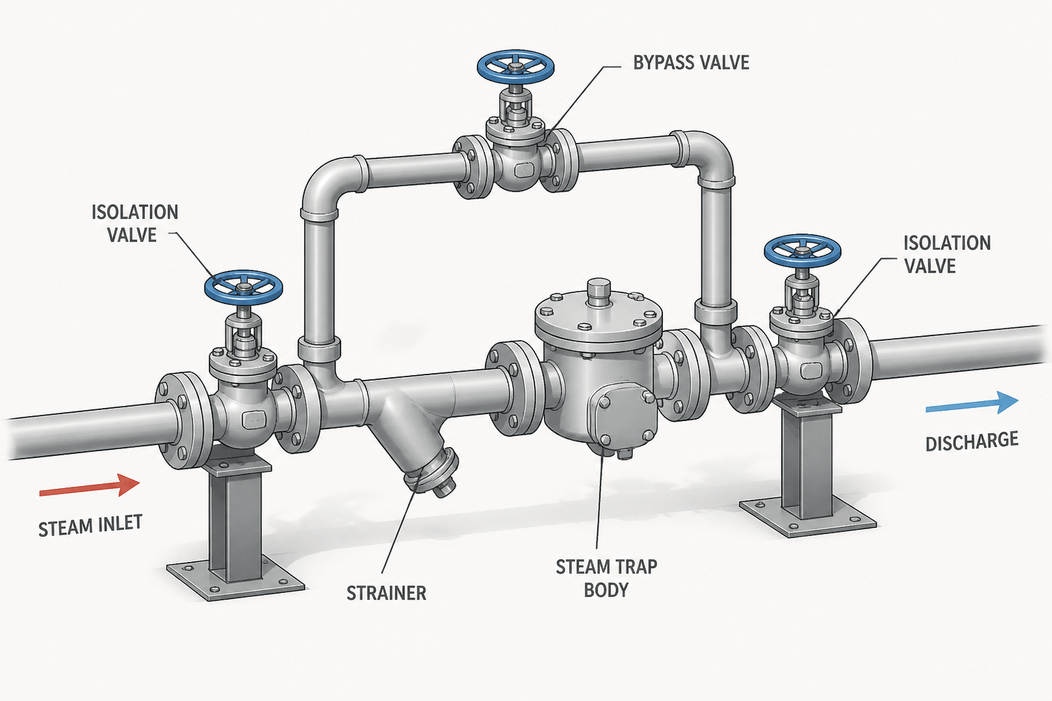
Clear steam trap piping documentation connects process intent with the physical arrangement shown in the model. The drawing should help a reviewer understand where condensate enters, how the trap is isolated and serviced, whether a bypass exists, and where the discharge goes.
Use the existing project documents as the controlling source for component selection, line identity, operating position, and discharge requirements. The guidance below is intended to improve CAD communication and review discipline, not to replace the approved P&ID, piping specification, or equipment data.
Steam trap piping can look simple in a plant model, but a small trap station often combines several functions: condensate removal, isolation, straining, testing, bypassing, venting, and discharge routing. If those functions are compressed into a crowded detail or drawn with ambiguous symbols, the design intent becomes difficult to review and build.
This guide explains how to document steam trap piping in CAD without replacing the project piping specification, approved P&ID, or equipment requirements. The objective is not to prescribe one universal arrangement. Instead, it is to provide a repeatable way to show the selected arrangement clearly and to identify the information that must be confirmed before modeling.
What a steam trap station represents
A steam trap station is the piping and valve assembly used to remove condensate from a steam system while limiting the loss of live steam. The station may include the trap itself, upstream and downstream isolation valves, a strainer, a check valve, a test connection, a bypass, a drain, or a discharge header connection.
The exact combination depends on the service, trap technology, maintenance philosophy, discharge destination, and project standard. A CAD modeler should therefore begin with the process documents and piping material specification rather than selecting a generic block from a library.
Separate the functional elements before drawing
Before creating geometry, identify the intended flow path and divide the station into functional elements. This helps prevent a common drafting error: showing a visually plausible group of valves without making the operating sequence understandable.
- Inlet connection: Identify where condensate enters the station and whether the connection comes from a drip leg, equipment outlet, tracing circuit, or another collection point.
- Isolation: Determine which valves isolate the trap for inspection or replacement. Show their normal operating intent if that information is controlled by the P&ID or operating philosophy.
- Straining: If a strainer is required, verify its location, flow direction, drain orientation, and maintenance access.
- Trap body: Use the approved component representation and show the flow direction. Do not infer the trap type from appearance alone.
- Discharge control: Check whether a downstream check valve, sight glass, test valve, or other component is required by the project documents.
- Outlet destination: Identify whether the discharge goes to a condensate return, flash vessel, drain system, collection header, or another defined destination.
Writing this sequence as a short equipment or line-list note before modeling can expose missing information early.
How to show the trap in a P&ID and CAD model
The P&ID establishes the process function and component identity. The CAD model and detail drawing then add physical information such as orientation, elevation, support, access, and connection geometry. These representations should agree, but they should not be treated as interchangeable.
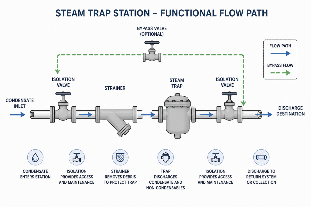
In the model, make the trap flow direction unmistakable. Use the manufacturer or project-approved symbol and orient the component so that the inlet and outlet are not confused when viewed from the selected direction. Where the trap has a defined installation orientation, show that orientation in the model or detail rather than relying on a general note.
Do not use a generic valve block to represent a trap. A generic block can hide the connection type, face-to-face length, maintenance envelope, and directional requirements that affect the surrounding piping. If the exact component is not yet selected, use a controlled placeholder with a clear status rather than silently substituting an assumed geometry.
Representing isolation valves and strainers
Isolation valves should be modeled as functional components, not merely as breaks in the line. Their location affects access, removable spool length, handwheel clearance, and the ability to isolate the trap without disturbing adjacent equipment.
When a strainer is present, check the orientation of the basket or blowdown connection. A strainer symbol may be sufficient on a P&ID, but a three-dimensional model needs enough information to show how the item will be installed and serviced. Include a drain or blowdown connection when it is part of the approved arrangement, and check that the connection does not point into steelwork, insulation, or another obstruction.
For compact stations, use a detail view or enlarged model representation when the normal plant view cannot communicate the valve and strainer arrangement. The detail should remain linked to the line or equipment reference so that reviewers can locate it quickly.
Bypass piping: show function, not just geometry
A bypass is not automatically required for every steam trap station. Where a bypass is specified, its purpose may be startup, temporary drainage, testing, warm-up, or continued operation during trap maintenance. The reason matters because it influences valve selection, normal position, discharge routing, and operating notes.
In CAD, show the bypass as a separate flow path with its own valves and line identity. Avoid drawing it so close to the main trap path that the two routes appear connected incorrectly. The bypass should have visible tie-in points, a consistent centerline, and enough separation for dimensions and callouts.
If the bypass is normally closed, do not rely only on a general valve symbol to communicate that condition. Use the project-approved notation or a specific operating note. The model should also make it possible to identify which valves belong to the bypass rather than the primary trap path.
Discharge routing and drainage considerations
The discharge side is often where an otherwise correct trap station becomes difficult to construct or review. Confirm the destination and routing requirements before deciding how to orient the trap. Discharge piping may need to account for gravity drainage, backpressure, flashing, temperature effects, noise, or segregation from incompatible systems. These are engineering and project requirements, not assumptions to be resolved by drafting convention.
Show the outlet route far enough to establish its destination or connection point. If the line continues to a remote header, identify the continuation using the project drawing convention and preserve the line identity. If the discharge terminates at a drain funnel or open drain arrangement, show the termination detail required by the project.
Where a drain connection is provided, make its low point, valve, and outlet direction clear. Do not place a drain symbol at an arbitrary location merely to fill a typical detail. A drain is useful only when its position supports the intended operation and maintenance procedure.
CAD representation checklist
| Review item | What to verify |
|---|---|
| Flow direction | Inlet, trap outlet, bypass route, and discharge direction are unambiguous. |
| Component identity | Trap, valves, strainer, check valve, and test items match the approved data. |
| Line identity | Each connected line has the correct service, specification, and continuation reference. |
| Access | Valve operators, removable components, drains, and test points have practical access. |
| Orientation | Trap and strainer installation orientation agrees with the selected component requirements. |
| Discharge | The outlet destination and any required separation or drainage features are shown. |
| Model connectivity | There are no accidental gaps, overlapping solids, or unconnected bypass branches. |
| Documentation | Notes, tags, symbols, and detail references agree across the P&ID, model, and drawings. |
Common drafting mistakes to avoid
- Reversing the trap: A symmetrical-looking symbol or block can conceal an incorrect flow direction.
- Omitting the discharge destination: A trap outlet that stops at the edge of a detail is difficult to review unless the continuation is explicitly identified.
- Using an unapproved typical: Trap stations vary by service and project philosophy; a typical detail should not override the line-specific documents.
- Overlapping valves in the model: Compact geometry can make operators, flanges, and removable parts appear inaccessible.
- Leaving bypass intent undefined: A bypass without a stated function can create confusion during operation and review.
- Ignoring maintenance removal: The CAD arrangement may fit in the line but still lack a practical path for removing the trap or strainer.
A practical workflow for review
Start by marking the trap station on the P&ID and identifying every associated component. Confirm the line specification, component data, discharge destination, and operating notes. Build the primary flow path first, then add isolation, straining, testing, bypass, and drainage features as separate functions.
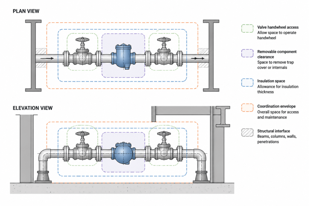
Next, review the station in plan, elevation, and three-dimensional views. Check flow direction, operator access, removable lengths, support interfaces, insulation allowances, and nearby structural or equipment conflicts. Finally, compare the model against the P&ID and line list node by node. Any difference should be resolved through the project change process rather than hidden with a drafting note.
A well-detailed steam trap station does more than display a valve cluster. It communicates how condensate is collected, isolated, tested, discharged, and maintained. Clear functional separation and disciplined data checking make the detail easier to fabricate, review, and coordinate with the rest of the piping system.
How to review a steam trap station detail
A useful review separates three questions that are often mixed together: what the station does, what components it contains, and whether the physical arrangement can be operated and maintained. Reviewing these questions separately makes omissions easier to identify.
Confirm process intent first
Start with the condensate source, intended flow path, and discharge destination. Then verify that the P&ID, line list, model, and detail drawing use matching tags and continuation references. A visually tidy arrangement is not sufficient if its process identity is unclear.
Use the model to expose physical constraints
The three-dimensional model should make access, orientation, removable components, support interfaces, insulation allowances, and nearby obstructions visible. These checks are especially important where a compact station has several valves, a strainer, a test connection, or a bypass in a limited space.
Keep assumptions visible
If the trap or an associated component has not been selected, identify the placeholder and its status. Do not allow an assumed block, symbol, or connection arrangement to appear as approved design information. Clear status notation helps process, piping, operations, and construction reviewers understand what remains open.
Questions for a coordinated CAD review
- Can a reviewer follow the primary condensate route without tracing ambiguous geometry?
- Are the bypass and primary paths visually and functionally distinct?
- Can the trap, strainer, valves, and test points be identified from the applicable views?
- Is the discharge continuation or termination shown according to the project convention?
- Can maintenance personnel reach and remove the intended components?
- Do the model, P&ID, line list, and detail notes agree without relying on undocumented assumptions?
Frequently asked questions
What should a steam trap station detail show?
It should show the approved trap representation, flow direction, connected isolation and auxiliary components, bypass if specified, drainage features, line identity, and discharge destination or continuation. The exact arrangement must come from the project documents.
Is a bypass required for every steam trap station?
No. A bypass should be shown only when it is part of the approved arrangement. Its purpose, valve condition, and discharge routing should be defined rather than assumed from a generic typical detail.
Why is discharge routing important in CAD?
The outlet route affects how the station connects to the condensate or drain system and may influence drainage, flashing, backpressure, temperature, noise, and system separation requirements. CAD should communicate the required destination and connection clearly.
Can a generic valve block represent a steam trap?
A generic block should not silently substitute for an approved trap representation. It can obscure flow direction, connection information, installation orientation, maintenance space, and surrounding geometry. If selection is incomplete, use a controlled placeholder with clear status.
How should a compact trap station be documented?
Use an enlarged detail or model representation when the normal plant view cannot communicate the arrangement. Keep the detail tied to the relevant line or equipment reference and ensure that its notes and tags agree with the P&ID and model.
What is the most common CAD error in trap station documentation?
Common errors include reversed flow direction, unclear bypass intent, omitted discharge destinations, inaccessible operators, overlapping components, and missing maintenance removal space. A coordinated review should check both function and physical access.