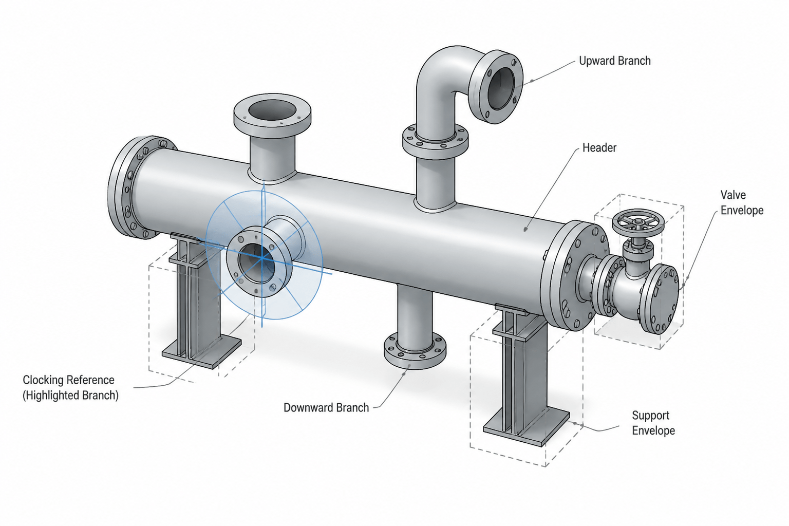
Clear branch orientation is essential when piping geometry must be understood by designers, reviewers, fabricators, and field installers. A branch can be routed to the correct destination and still create problems if its circumferential position, facing direction, or surrounding access requirements are unclear.
This guide explains how to communicate branch direction and clocking in CAD without relying on a single drawing view. It also connects orientation decisions to equipment interfaces, maintenance space, supports, insulation, fabrication, and coordinated project documentation.
Why piping branch orientation matters
A branch connection is more than a line leaving a header. Its orientation affects valve access, instrument visibility, drainage, venting, support placement, weld access, insulation, and the amount of space required around nearby equipment. A branch that appears acceptable in a plan view may point into a structural member, turn toward an inaccessible side of a valve, or create an unwanted low point when viewed in elevation.
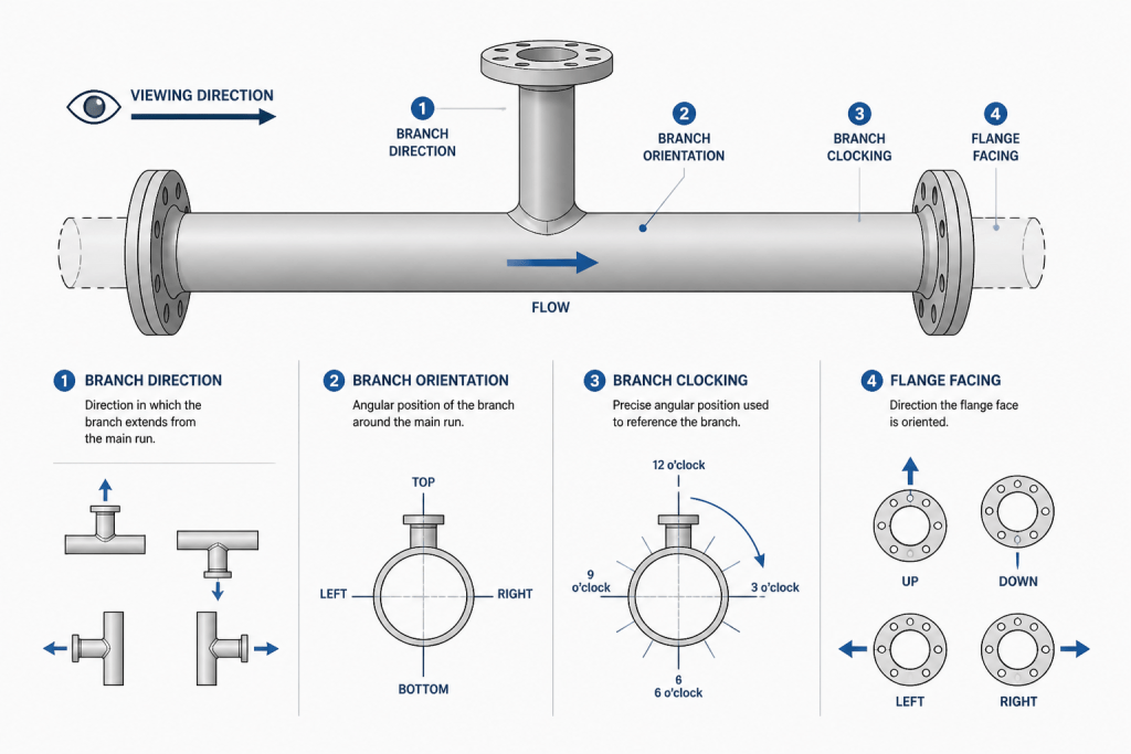
In CAD, piping branch orientation describes the direction in which a branch leaves the run pipe. Clocking describes its rotational position around the run, commonly expressed using a clock-face reference. These concepts are especially important for small-bore connections, instrument takeoffs, drains, vents, and branches connected to equipment nozzles.
The purpose of clocking is not to make a drawing look more detailed. It is to remove ambiguity between the process intent, the three-dimensional model, the fabrication drawing, and the field installation.
Branch direction, clocking, and orientation are different
These terms are related but should not be treated as interchangeable.
| Term | Meaning in CAD and piping work | Typical review question |
|---|---|---|
| Branch direction | The path followed by the branch after it leaves the run or header. | Does the branch route toward the correct destination? |
| Branch orientation | The spatial position of the connection relative to the run, equipment, or plant coordinates. | Is the connection pointing up, down, sideways, or at an intentional angle? |
| Clocking | A rotational reference used to communicate the circumferential position around a pipe or nozzle. | Can another person reproduce the same orientation? |
| Facing | The direction in which an end connection, flange face, valve, or instrument port is directed. | Is there enough access for assembly and operation? |
A branch may have the correct destination but the wrong clocking. For example, a drain route could reach the intended low point while the valve handle faces a support or the branch connection interferes with insulation. Reviewing only the line centerline is therefore insufficient.
Establish the orientation convention before modeling
Clock positions are useful only when the viewing convention is clear. A clock reference may be defined while looking along the run in the direction of flow, looking toward the equipment, or looking from a specified end of the spool. Different projects and fabrication teams can use different conventions.
Before adding clocking information to a model or drawing, confirm:
- Which direction is used as the viewing direction.
- Whether the reference is based on flow direction, a drawing view, or a stated north or plant-coordinate direction.
- How vertical-up and vertical-down positions are represented.
- How angled branches are described when they do not fall on a principal plane.
- Whether the piping specification or project modeling standard defines a preferred notation.
Do not rely on a clock position by itself when the reference could be misunderstood. Pair it with a clear view, an orientation note, coordinates, a branch angle, or a model property as appropriate.
Inputs to check before setting branch orientation
Branch orientation should be developed from more than the process line route. Review the available design information in a deliberate order.
Process and piping information
- Confirm the branch connection type, nominal size, piping class, and material requirements from the current project data.
- Determine whether the branch is intended for flow, draining, venting, sampling, instrumentation, utility service, or future use.
- Check whether a valve, spectacle blind, instrument, removable spool, or other component follows the branch.
- Identify any required slope direction or low-point and high-point requirements.
Physical and access information
- Review equipment nozzles, platforms, ladders, handrails, structural steel, cable trays, and adjacent pipe runs.
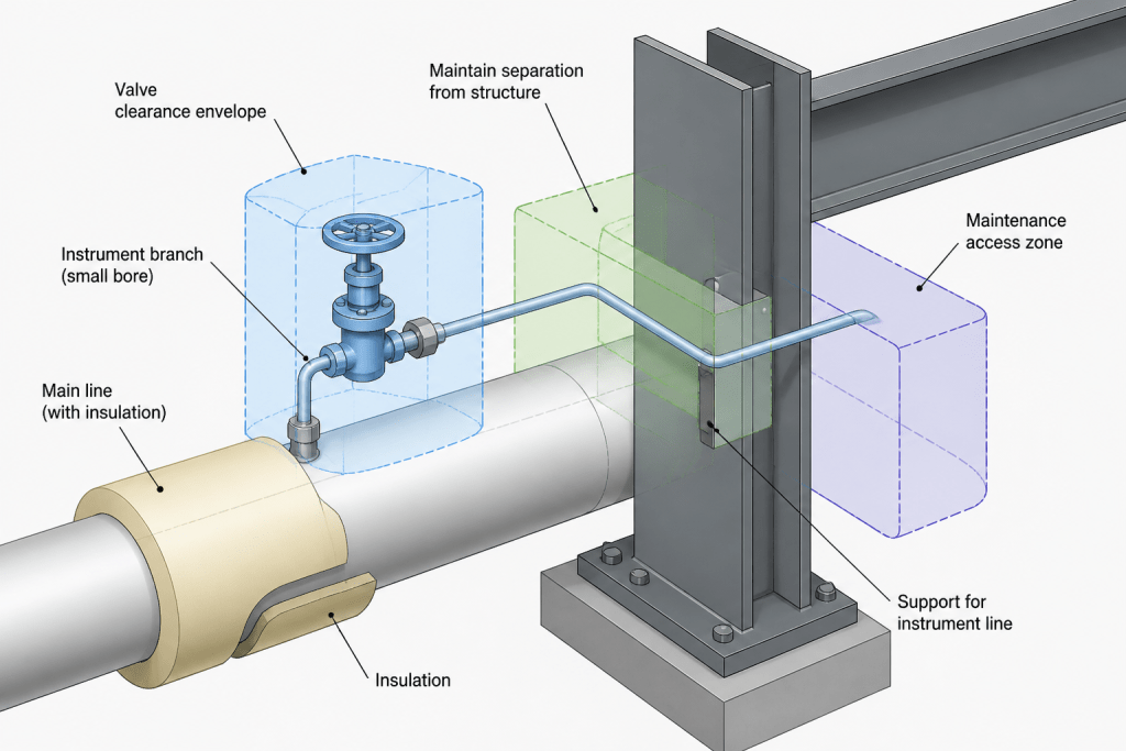
- Check space for bolting, welding, coating, insulation, heat tracing, operation, removal, and maintenance.
- Consider the support arrangement. A branch location can affect local flexibility, loads, and the placement of guides or restraints.
- Confirm whether the branch must be visible or reachable from an operating or maintenance position.
The correct orientation is usually the result of coordinating these constraints, not simply rotating a fitting until it clears another object.
How to model a branch clearly in CAD
Start with a stable reference for the run pipe. Use the run centerline, plant coordinates, and relevant equipment or structural references rather than relying on screen orientation. Then place the branch connection at the verified station along the run and define its direction in three-dimensional space.
For a branch that lies on a principal plane, show the relationship with an appropriate plan, elevation, or section view. For a branch that rotates around the run, use a combination of model orientation, an isometric representation, and a callout or note. The drawing should communicate both where the branch starts and where it points.
When the branch includes an elbow or offset, do not assume the first visible segment proves the orientation of the connection. The fitting may change the apparent direction. Use centerlines, endpoint coordinates, orientation properties, or a dedicated detail view to make the connection unambiguous.
For flanged or threaded connections, model the end orientation as well as the branch centerline. A flange may be correctly located while its bolt-hole orientation conflicts with the intended assembly position. Likewise, an instrument connection may have the correct centerline but an inaccessible port or transmitter display.
Choosing between clocking and coordinate dimensions
Clocking is efficient for communicating circumferential orientation around a cylindrical run. Coordinate dimensions are generally stronger when the branch must be located relative to equipment, steel, building grids, or a fabrication datum. Many projects use both.
| Situation | Useful primary communication | Additional clarification |
|---|---|---|
| Simple branch on a clearly shown run | Plan or elevation view with a branch direction | Add a clocking note if the view does not establish rotation. |
| Small-bore instrument connection | Detail view with orientation and access indication | Show the instrument or tubing route when it affects clearance. |
| Branch at equipment or a nozzle | Equipment reference, coordinates, and nozzle orientation | Verify the equipment vendor’s orientation information. |
| Spool fabrication connection | Isometric, weld locations, and endpoint orientation | Use a defined datum or match reference for shop and field fit-up. |
| Drain or vent connection | Elevation and slope-related detail | Confirm the actual high point or low point rather than relying only on clocking. |
Common CAD mistakes
Using the screen view as the orientation reference
A rotated isometric view can make a branch appear to be in a different clock position. Screen position is not a reliable engineering datum. Use model coordinates, named views, and explicit references.
Omitting the viewing direction
A note such as “branch at the three o’clock position” is incomplete if the reader does not know which end of the run is being viewed. State the reference direction or use a view that makes it clear.
Checking only the centerline
Centerline clearance does not prove that valves, flanges, actuators, insulation, or instruments will fit. Review the physical envelope and the maintenance path.
Assuming the branch fitting determines the final route
A tee, olet, weldolet, sockolet, or other branch fitting defines a connection, but the downstream piping still needs a coordinated route. Confirm the actual branch axis and the orientation of any attached components.
Failing to update related documents
Changing a branch clocking can affect isometrics, spool drawings, support locations, material takeoffs, stress models, instrument hook-ups, and equipment nozzle schedules. Treat the change as a coordinated data update rather than a local drafting adjustment.
A practical review checklist
Use the following checklist during model review or drawing checking:
- Is the branch connected at the intended run station and line?
- Is the branch direction consistent with the process and routing intent?
- Is the clocking convention or viewing direction defined?
- Do plan, elevation, section, and isometric views agree?
- Are valves, flanges, instruments, and removable components oriented for access?
- Does the branch avoid structural, electrical, insulation, and maintenance conflicts?
- Are slope, venting, draining, and pocket concerns addressed?
- Are weld locations and spool breaks still practical after the orientation is set?
- Do support locations and restraint concepts remain coordinated?
- Have associated drawings, schedules, models, and review comments been updated?
Final takeaway
Good piping branch orientation in CAD is a communication task as much as a modeling task. Define the reference convention, model the branch in three dimensions, check the complete component envelope, and use views or dimensions that another engineer, designer, fabricator, and installer can interpret consistently. Clocking is valuable, but it should support—not replace—clear geometry, coordinates, access checks, and coordinated project data.
How to use this guide during design review
Branch orientation is best reviewed as a coordination issue rather than an isolated drafting detail. Begin with the design intent, establish the reference convention, and then check how the selected orientation affects the complete assembly. This includes the branch fitting, downstream piping, valves, flanges, instruments, insulation, supports, and nearby access paths.
For drafting and modeling teams, the key distinction is between showing geometry and communicating intent. A model may contain an accurate branch axis, but a reviewer still needs to understand the viewing direction, the relevant datum, and the practical reason for the selected orientation. Clear views, notes, coordinates, and model properties should reinforce one another.
Why orientation changes deserve coordinated review
Rotating a branch can affect more than its local appearance. It may change the position of a valve or instrument, alter a spool interface, influence support placement, or create a conflict with equipment, structure, insulation, or maintenance access. A seemingly small CAD change can therefore require review of connected drawings, schedules, models, and fabrication information.
A useful review sequence is to confirm the branch purpose, verify the reference direction, inspect the surrounding physical envelope, and then compare all affected project documents. This approach helps separate a true routing improvement from a change that merely moves the conflict elsewhere.
Frequently asked questions
What is piping branch clocking?
Piping branch clocking is a way to describe the rotational position of a branch around the run pipe or equipment nozzle. It is meaningful only when the viewing direction or reference convention is clearly defined.
Is clocking enough to define a branch location?
Not always. Clocking communicates circumferential orientation, while coordinates, elevations, views, and equipment references may be needed to establish the complete location and direction.
Why should valve and instrument access be checked after setting branch orientation?
The branch centerline does not represent the full physical envelope of attached components. Valves, instruments, flanges, insulation, and removable parts may require access or clearance that is not apparent from the centerline alone.
How should an angled branch be documented?
Use a clearly identified model or drawing view together with suitable orientation information, such as a defined reference direction, coordinates, an angle description, or a dedicated detail. Avoid relying on an ambiguous clock note by itself.
What should be reviewed when branch clocking changes?
Review connected piping, valves, instruments, supports, spool breaks, weld locations, equipment interfaces, isometrics, fabrication documents, and any related models or schedules. The exact review scope depends on the project configuration.