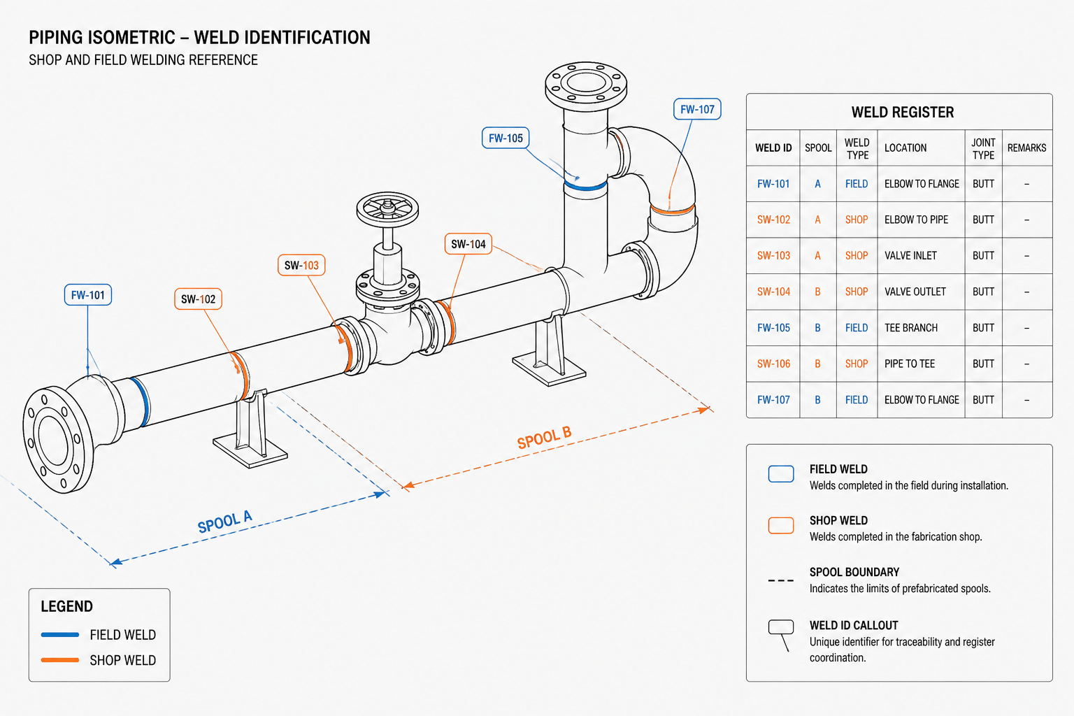
A piping weld map is the graphical connection between a piping drawing and the project records that control fabrication, inspection, repair, and turnover. When the map is clear, a reviewer can move from a weld ID on an isometric to the related spool, joint history, and inspection record without relying on guesswork.
This guide explains how to structure weld identification in CAD, distinguish weld locations from weld symbols, coordinate shop and field boundaries, and review the finished map before issue. The exact identification convention remains project-specific, so the approved register and drafting procedure should govern the final representation.
A piping weld map connects the graphical information on a piping drawing with the records used for fabrication, inspection, and turnover. It identifies individual welds, shows where they occur, and provides a controlled way to associate each weld with a spool, joint record, inspection result, or repair history.
A weld map is not the same as a collection of weld symbols. Weld symbols describe the type or treatment of a weld on a drawing. A weld map adds identification and tracking information so that a reviewer can locate a joint and follow its status through the project workflow.
When prepared carefully, a weld map helps answer practical questions: Which joints belong to a spool? Which joints are field welds? Where is a weld located on the isometric? Has the joint been inspected? Does the weld register agree with the drawing and the fabrication package?
What a piping weld map should accomplish
The main purpose of a weld map is traceability. Each tracked weld should have a unique identifier that can be located on the drawing and matched to the project’s weld register or inspection documentation.
A useful weld map should make several relationships clear:
- The weld ID and its exact location on the piping geometry.
- The connection between the weld and a spool, assembly, or field installation boundary.
- Whether the joint is a shop weld, field weld, tie-in weld, or another project-defined category.
- The components or pipe ends joined by the weld.
- The inspection, repair, or acceptance status recorded outside the drawing.
- The drawing revision or model state in which the weld identification was created or changed.
The drawing does not need to contain every inspection detail. Its job is to provide an unambiguous graphical key that agrees with the controlled records.
Weld map versus weld symbols
Weld symbols communicate welding information such as the applicable joint representation, side of the reference line, or project-defined weld treatment. A weld map focuses on identification and location. In practice, the two may appear together, but they serve different purposes.
| Item | Primary purpose | Typical CAD use |
|---|---|---|
| Weld symbol | Describe the weld representation or required treatment | Place near the joint or reference location |
| Weld ID | Identify one trackable joint | Place as a readable callout tied to the weld location |
| Weld map | Show and organize the complete set of tracked joints | Combine identifiers, boundaries, notes, and a weld list |
| Weld register | Store the controlled record for each weld | Maintain outside or alongside the drawing according to project practice |
A common drafting error is to assume that a weld symbol alone provides traceability. It may show that a weld exists, but without a unique identifier it can be difficult to match the joint to fabrication or inspection records.
Establish the weld identification scheme before drafting
Before placing labels in CAD, confirm how weld IDs are assigned. The naming method may be based on a line number, spool number, drawing number, area, or a project-wide sequence. The exact convention is project-specific, so the drafter should use the approved weld register or drafting standard rather than inventing a local pattern.
Define the following items before starting:
- Whether IDs are assigned to every weld or only to welds requiring tracking.
- How shop welds, field welds, tie-ins, and special joints are distinguished.
- Whether branch connections receive separate weld IDs for each joint.
- How socket, threaded, seal, or other non-butt connections are represented if they are included in the tracking system.
- How revised, deleted, or superseded weld IDs are handled.
- Which attributes must match the weld register, such as spool reference, line number, joint type, or inspection category.
Do not use visual position alone as an identifier. A label such as “the weld near the valve” is not reliable when the drawing changes or when similar components appear repeatedly.
Place weld IDs at clear geometric locations
On an isometric, place the weld ID close enough to the joint that the relationship is obvious, but far enough away to avoid covering the pipe line, component symbol, dimensions, or other callouts. Use a consistent leader style when the label cannot sit directly beside the joint.
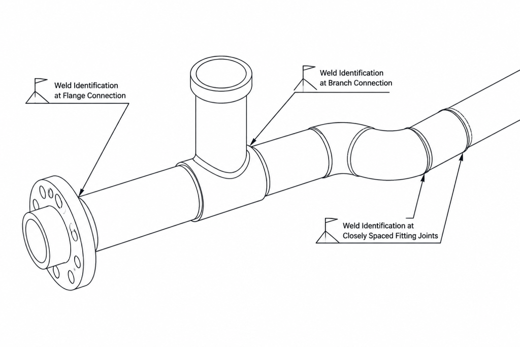
The leader should terminate at the actual weld location, not at a nearby component unless the project drafting method explicitly uses a shared reference. This distinction matters around flanges, valves, branch connections, and short spool segments where several joints may be close together.
For crowded areas, use a coordinated callout zone or a weld index rather than stacking several labels on top of the geometry. A clean layout is more valuable than forcing every identifier into a small open space.
Locations that require extra care
- Flanged joints: distinguish a weld at the pipe-to-flange connection from the bolted flange connection itself.
- Branch connections: identify the branch-to-run joint and any separate connection at the branch component.
- Closely spaced fittings: verify which weld belongs to which component end.
- Spool breaks: show the boundary clearly so a fabrication weld is not confused with a field weld.
- Field tie-ins: coordinate the weld ID with the existing-to-new connection and the construction package.
Show spool and field-weld boundaries separately
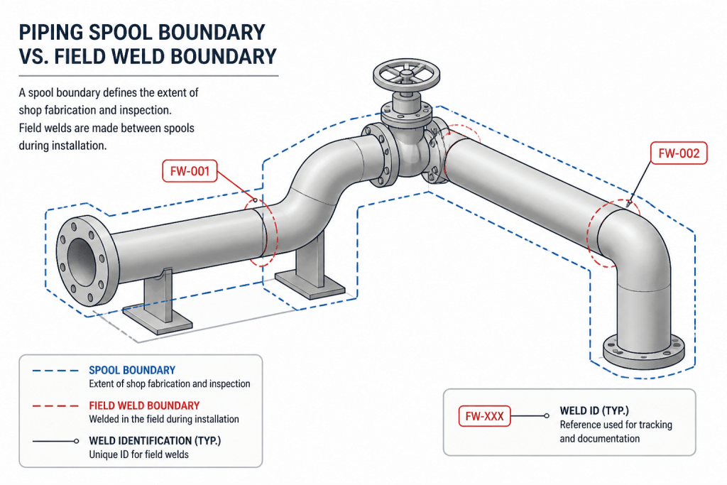
A weld map becomes much more useful when it distinguishes fabrication scope from site installation scope. Use the project-approved graphical convention for spool breaks, field welds, and installation boundaries. The convention may involve line types, symbols, notes, or a combination of methods.
Do not rely on color alone. Printed drawings, monochrome exports, and document-control systems may remove color information. A field weld should remain identifiable through linework, labels, or a legend even when the drawing is reproduced in black and white.
Check that the boundary agrees with the spool drawing and the fabrication plan. A field weld shown on an isometric but omitted from the spool breakdown can create confusion during assembly. Conversely, a weld assigned to a spool but shown as a field joint can affect material release, inspection planning, and installation sequencing.
Build the weld list from the same controlled data
A weld list or weld register should not be typed independently from the drawing if the project workflow can avoid it. The preferred approach is to use shared attributes or a controlled export so that the weld ID, line number, spool reference, and status fields remain consistent.
At minimum, compare the drawing against the weld register for:
- Missing weld IDs on the drawing.
- Duplicate IDs or IDs assigned to more than one joint.
- Welds listed in the register but absent from the current drawing.
- Welds shown on the drawing but absent from the register.
- Incorrect spool or field classification.
- Inconsistent line, area, or component references.
CAD block attributes, object data, or model properties can support this process, but automation does not remove the need for visual review. A data field may be populated correctly while a leader points to the wrong joint.
Review a weld map before issue
Perform the review in several passes. First, trace the piping route and confirm that every required tracked joint has an identifier. Next, inspect dense areas such as branches, valve stations, flange pairs, and spool boundaries. Then compare the identifiers and classifications with the weld register.
Also check drawing readability at the final plotted scale. A weld ID that is clear in model space may become unreadable after viewport scaling or PDF export. Leaders should not cross unrelated lines, and revisions should not leave obsolete IDs visible beneath new annotations.
Finally, verify that the map is coordinated with the fabrication and inspection documents. The drawing is one part of the traceability chain. Its value depends on consistent identifiers across the isometric, spool drawing, weld register, inspection report, repair record, and turnover package.
Practical CAD checklist
- Use the approved weld-ID convention.
- Assign each tracked joint one unique identifier.
- Point each leader to the actual joint location.
- Separate weld symbols from weld-identification callouts when their purposes differ.
- Show shop and field boundaries using more than color alone.
- Coordinate branch, flange, and closely spaced fitting welds carefully.
- Compare drawing IDs with the controlled weld register.
- Check revised and deleted welds so obsolete labels are removed or clearly superseded.
- Review the plotted output, not only the editable CAD file.
A well-structured piping weld map turns a complex isometric into a traceable fabrication and inspection reference. The most reliable results come from treating weld identification as shared project data, placing it precisely in CAD, and checking the graphical map against the controlled records before issue.
How weld-map information moves through the project
A weld map works best when it is treated as shared project data rather than as isolated drafting text. The CAD drawing provides the spatial reference, while the weld register and inspection records provide the controlled status and history. These sources should agree without requiring a reviewer to interpret informal labels or reconstruct the intended relationship.
Separate location, identity, and status
These three ideas are related but should not be confused. The location shows where the joint occurs in the piping geometry. The identity gives that joint a controlled reference. The status records what has happened to it, such as inspection, repair, or acceptance. Keeping these roles distinct makes both the drawing and the supporting records easier to maintain.
Use the map as a handoff tool
Different project participants may use the same weld ID for different purposes. A fabricator may use it to organize shop work, an inspector may use it to locate examination records, and a turnover team may use it to confirm that the documentation package is complete. The label should therefore remain stable and readable across drawing revisions and document exchanges.
Watch for data that looks correct but points incorrectly
Automated attributes and exports can reduce transcription errors, but they cannot prove that a leader terminates at the intended joint. Visual checking remains essential around branches, flanges, valves, short spool segments, and crowded isometric areas. A correct identifier attached to the wrong graphical location is still a traceability failure.
Review the map as a document-control product
Before issue, review both the editable CAD file and the plotted or exported document. Confirm that obsolete annotations are removed or clearly controlled, the legend remains understandable without color, and the weld list reflects the current revision. This review connects drafting quality with fabrication readiness and inspection-document completeness.
Frequently asked questions
What is the purpose of a piping weld map?
Its purpose is to identify tracked welds on a piping drawing and connect their locations with controlled fabrication, inspection, repair, and turnover records.
Is a weld map the same as a weld symbol?
No. A weld symbol communicates welding information or treatment, while a weld map adds identifiers, locations, boundaries, and record-tracking relationships.
Should every weld receive an ID?
That depends on the approved project procedure. Some projects track every weld, while others define specific joint categories for inclusion. The drafter should follow the controlled weld register and project convention.
How should field welds be shown in CAD?
Use the project-approved convention for field welds and spool boundaries. The distinction should remain clear through linework, labels, symbols, or notes and should not depend on color alone.
Can weld IDs be generated automatically?
Controlled CAD attributes, model properties, or exports can support consistent identification. They should be checked against the drawing visually because automation may not detect a leader attached to the wrong joint.
What should be checked before a weld map is issued?
Check identifier uniqueness, leader locations, spool and field classification, branch and flange details, revision status, plotted readability, and agreement with the weld register and related inspection documentation.