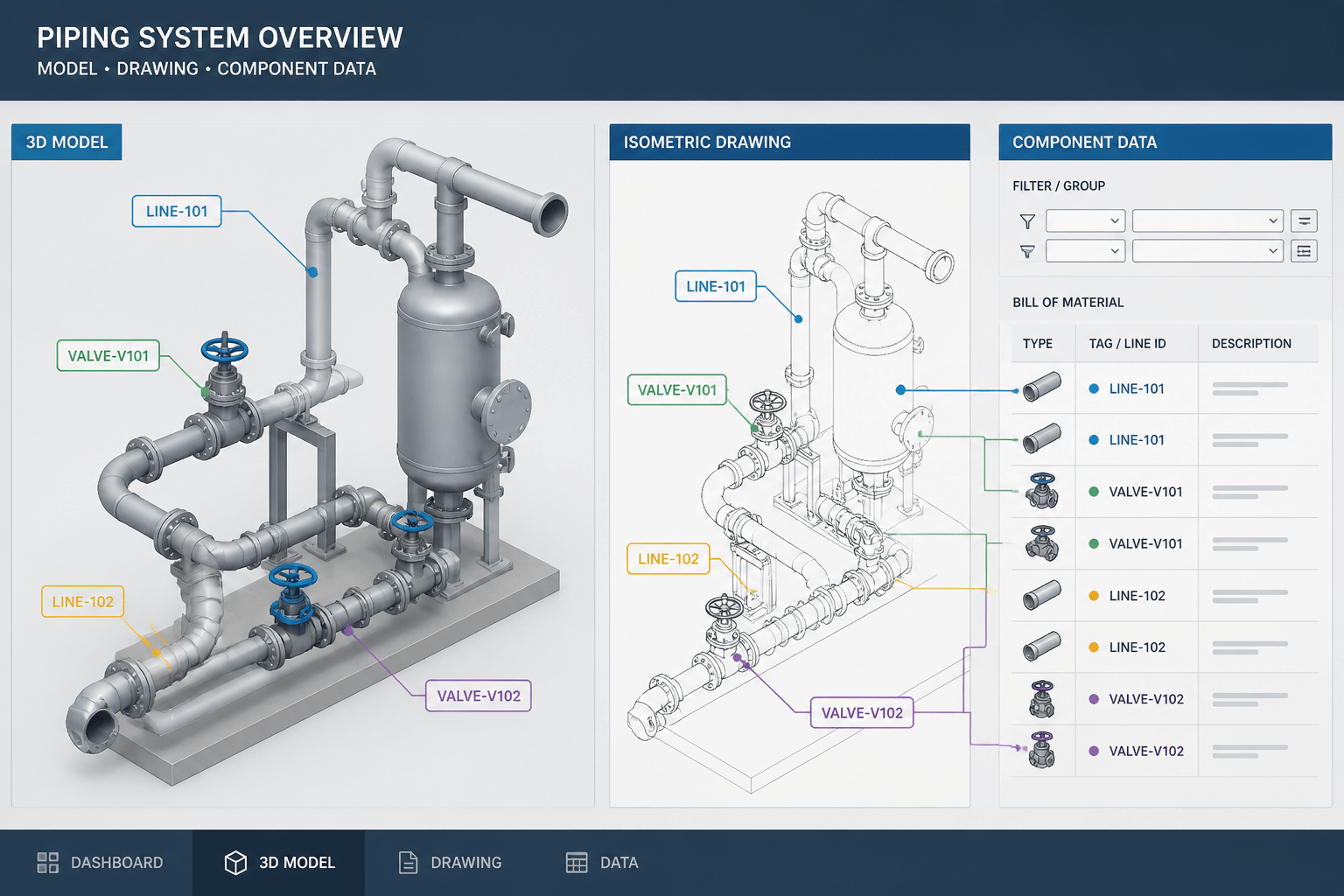
Piping model review is most effective when it examines both the visible arrangement and the information attached to each object. A model can appear coordinated while still containing mismatched line identities, incomplete attributes, incorrect component assignments, or document outputs that no longer reflect the current design.
This guide explains a practical approach to piping CAD model QA. It focuses on traceable comparisons between the model, approved engineering inputs, drawings, schedules, and bills of material so that discrepancies can be identified, assigned, corrected, and rechecked before release.
The method is useful for designers, piping engineers, CAD administrators, document reviewers, and project teams responsible for dependable model-based deliverables. It also clarifies why visual review, data validation, and document reconciliation should be treated as related but separate activities.
A piping model can look complete and still contain information that does not agree across drawings, schedules, and fabrication documents. A valve may have the correct shape but the wrong tag. An isometric may show a component that is missing from the bill of material. A line may connect geometrically while carrying an incorrect size, material class, or specification.
Piping CAD model quality assurance is the process of checking these relationships before the model or its drawings are released. It is broader than visual drafting review and different from clash detection. The goal is to confirm that the model represents the intended system and that downstream documents can be produced from consistent data.
What piping CAD model QA should verify
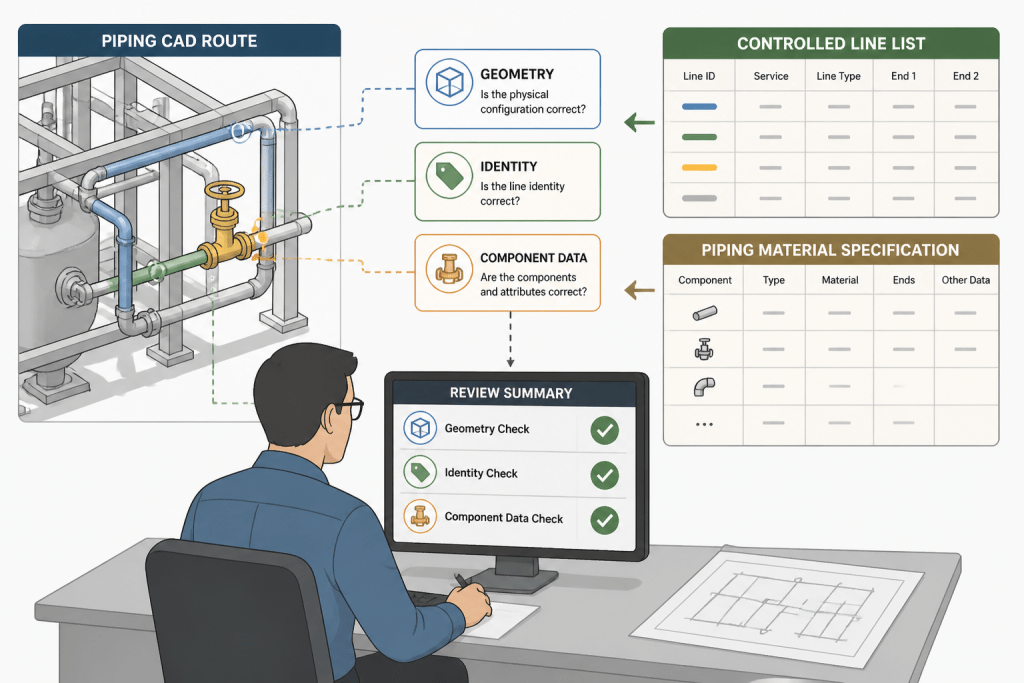
A useful review checks four related layers of information:
- Geometry: Are components located, oriented, connected, and represented correctly?
- Identity: Does each item have the correct tag, line association, service information, and component description?
- Engineering data: Do size, rating or class, material, end connection, insulation status, and other properties agree with the approved project inputs?
- Deliverables: Do plans, isometrics, bills of material, spool drawings, and schedules report the same design intent?
These layers are related, but they should not be treated as interchangeable. A geometrically correct model can contain incorrect metadata. A complete bill of material can still be based on an outdated routing arrangement.
Establish the review source of truth
Before checking the model, identify which document or controlled data source governs each type of information. The piping material specification may govern permitted components and materials. A line list may govern line identity and process attributes. Approved equipment information may govern nozzle locations and orientations. The model may govern the current spatial arrangement after design coordination.
Do not assume that one file is authoritative for every property. Create a short review matrix that identifies the controlling source for each data group. This prevents reviewers from resolving discrepancies by preference or by whichever document is easiest to access.
| Data group | Typical comparison source | QA question |
|---|---|---|
| Line identity and service | Approved line list or process documentation | Does the model identify the same line and service? |
| Component selection | Project piping material specification | Is the modeled component permitted for the assigned specification? |
| Equipment connection | Approved equipment or nozzle information | Does the pipe meet the correct connection at the correct orientation? |
| Quantity and description | Model extraction, isometric, or bill of material | Are counts, descriptions, and identifiers consistent? |
Use a controlled comparison workflow
1. Freeze the review set
Record the model revision and the revisions of the documents being compared. A discrepancy may be a genuine design error, or it may simply result from comparing a current model with an earlier line list or drawing. Reviewers should be able to identify the exact data set used for the check.
Separate design changes from QA corrections. A changed route may require engineering approval, while a missing tag may be a drafting correction. Mixing both types of issue in one unstructured markup set makes closeout difficult.
2. Check line continuity and identity
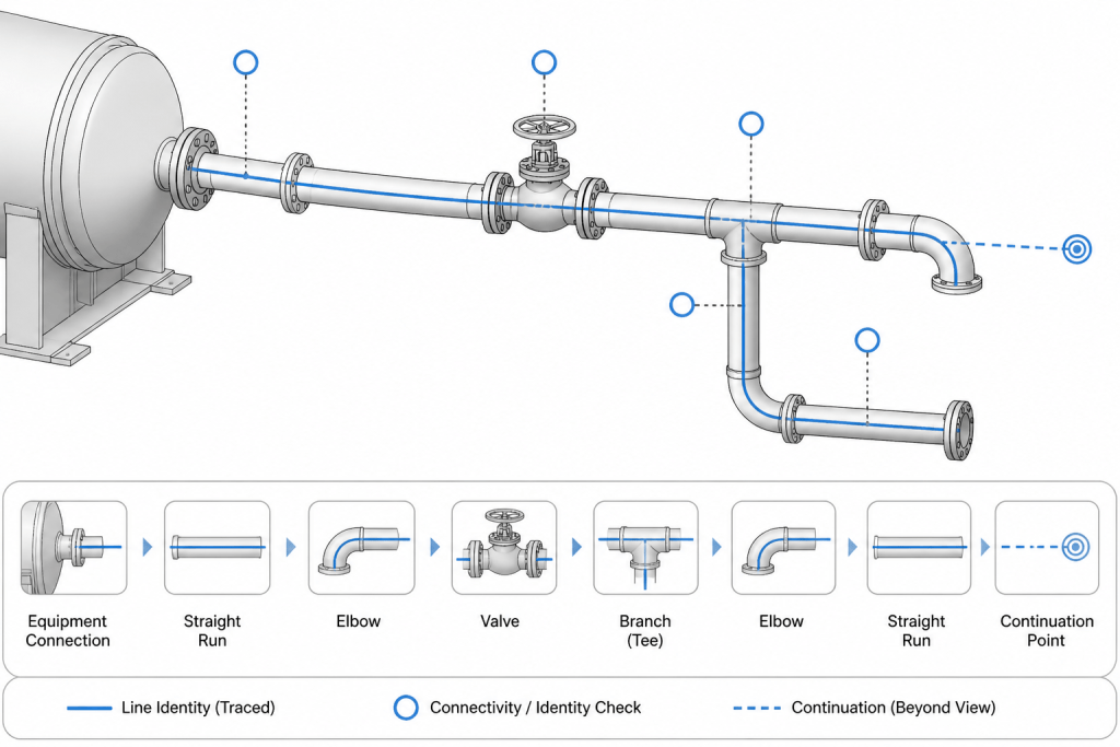
Review each line as a connected path rather than checking isolated components. Start at a defined endpoint and follow the route through fittings, valves, branches, instruments, and termination points. Confirm that the line number or identifier remains consistent unless a documented specification or service break occurs.
Look for common data failures:
- A component assigned to the wrong line after a copy or split operation.
- A branch that has geometry but no line or service assignment.
- A line that changes size or specification without a visible transition or documented reason.
- An equipment connection modeled at the wrong nozzle even though the pipe appears to reach the equipment.
- A continuation that carries a different identifier on the next drawing or model area.
3. Compare modeled components with expected components
Use the approved line information and piping specification to create an expected component set for each route. This is not a substitute for engineering review; it is a structured way to find omissions and unexpected additions.
Check component type, nominal size, end connection, material or specification assignment, and orientation. Pay particular attention to items that are easy to overlook in a crowded model, such as reducers, branch fittings, vents, drains, strainers, spectacle blinds, temporary items, and small-bore connections.
Do not judge a component only by its displayed symbol. CAD blocks and parametric parts can look similar while carrying different descriptions or connection data. Review the properties that will be used by extraction tools and drawing annotations.
4. Reconcile tags and attributes
Tags should be unique where the project requires uniqueness and should follow the same naming logic in the model, drawings, schedules, and inspection records. Check both visible annotations and stored object attributes. A correct label placed beside the wrong object is still a data error.
Useful checks include:
- Duplicate component tags.
- Missing tags on items that require identification.
- Tags that do not match the equipment, instrument, or valve register.
- Inconsistent capitalization, separators, or suffixes that affect sorting and searching.
- Attributes that were copied from a neighboring component and were not updated.
5. Compare the model with generated documents
Generate a fresh extraction from the reviewed model where the software workflow permits it. Compare the result with the latest isometric, plan, schedule, or bill of material. Avoid relying only on an old plotted sheet because it may not represent the current database state.
Compare by identifier first, then by description and location. Quantity differences should be investigated rather than automatically treated as errors. A bill of material may intentionally exclude certain items, combine similar components, or report items under a project-specific grouping rule. The governing extraction method must be understood before quantities are corrected.
Review geometry and data together
Some of the most important checks occur where geometry and metadata interact. Examples include a flange that is modeled with the wrong facing, a valve whose flow direction conflicts with the line intent, or an instrument connection that has the right tag but is attached to the wrong branch.
For each notable component, ask three questions:
- Is the object physically located and oriented as intended?
- Is it connected to the correct upstream and downstream objects?
- Does its stored data describe the object actually shown?
This approach also helps distinguish a visual representation issue from a model-data issue. A symbolic representation may be acceptable on a general arrangement drawing while the fabrication model still requires complete connection and attribute data.
Record discrepancies so they can be closed
A useful QA log identifies the affected line, component, drawing or model area, discrepancy type, responsible discipline, required action, and review status. Include enough context for another person to reproduce the finding. Screenshots can help, but they should not replace a clear identifier and written description.
Classify findings consistently. For example, use categories such as geometry, connectivity, identity, specification, quantity, document synchronization, and drafting presentation. This reveals recurring process problems, such as frequent tag duplication after copying or repeated missing components at specification breaks.
Final release checks
Before release, confirm that closed findings were corrected in the model or in the proper controlling document, not merely hidden on a drawing. Regenerate affected outputs after changes. Then perform a focused recheck of the corrected area and any connected deliverables.
- Confirm the review revision and approval status.
- Verify that no unresolved critical discrepancies remain.
- Regenerate schedules and bills of material after model changes.
- Check that tags and line identifiers remain consistent across affected sheets.
- Archive the QA log with the reviewed deliverable set.
Effective piping CAD model QA is not a single visual pass. It is a controlled comparison between geometry, component data, governing inputs, and generated documents. When those relationships are checked deliberately, the model becomes a more reliable source for coordination, detailing, fabrication information, and future revisions.
How to make piping model QA more efficient
A repeatable review is easier to manage when the work is organized around traceability rather than visual appearance alone. The reviewer should be able to move from a line or component in the model to its governing input, then to the generated drawing or schedule, without relying on assumptions about which file is current.
Review by route and data relationship
Reviewing a complete route helps expose errors that are difficult to find when components are checked individually. Follow the route through its connections, changes, branches, valves, instruments, and termination points. At each significant object, compare the physical connection with the stored identity and engineering attributes.
This approach is particularly helpful when copied geometry, reused blocks, model splits, or coordinated revisions may have carried outdated information into a new location. The important question is not only whether an object looks correct, but whether it belongs to the intended line and reports the information expected by downstream tools.
Separate discrepancy discovery from discrepancy resolution
Finding a mismatch does not always determine the correct fix. The controlling source may indicate that the model is wrong, or it may reveal that an approved input or drawing requires a controlled update. Record the discrepancy first, identify the responsible discipline, and confirm the governing information before changing the model.
Use output-focused checks
Model QA should include the documents that other project participants will actually use. Reviewers should consider whether extracted descriptions, identifiers, quantities, and locations remain understandable and consistent in the relevant deliverable. A technically correct model can still create project risk if its extraction rules, annotations, or document synchronization are not understood.
Close the loop after corrections
Corrections should be followed by regeneration of affected outputs and a focused review of connected areas. This is important because a change to one component can affect line continuity, tags, quantities, adjacent drawings, or related schedules. A closed QA item should represent a verified correction, not simply a comment that has been removed from a markup set.
For long-term project value, retain the review matrix, discrepancy log, revision information, and evidence of the final check with the deliverable record. This creates a useful audit trail and helps identify recurring modeling or data-management problems on future work.
Frequently asked questions
What is piping CAD model QA?
Piping CAD model QA is the controlled review of piping geometry, connectivity, component identity, engineering attributes, and generated documents. Its purpose is to confirm that the model represents the intended system and can support consistent downstream deliverables.
How is piping model QA different from clash detection?
Clash detection looks for physical or spatial conflicts between modeled objects. Piping model QA also checks tags, line assignments, specifications, component data, quantities, document synchronization, and whether the modeled information agrees with approved project inputs.
Which documents should be compared with a piping model?
The comparison set depends on the project, but it commonly includes controlled line information, piping material requirements, equipment or nozzle information, plans, isometrics, schedules, spool drawings, and bills of material. Each data group should have an identified controlling source.
Why can a correct-looking component still be a QA problem?
CAD objects with similar graphics can carry different tags, descriptions, connection data, line assignments, or specification attributes. A visual check may therefore miss a data error that later affects annotations, extraction results, schedules, or fabrication information.
How should a QA discrepancy be documented?
Record the affected line or component, model or drawing location, discrepancy category, responsible discipline, required action, and review status. Include enough identifying information for another reviewer to reproduce the finding and verify its closure.
Should every bill of material quantity difference be corrected?
No. First confirm how the applicable extraction or reporting method groups, excludes, or combines items. A quantity difference may reflect a deliberate reporting rule, an outdated output, or a genuine model error, so it should be investigated before correction.