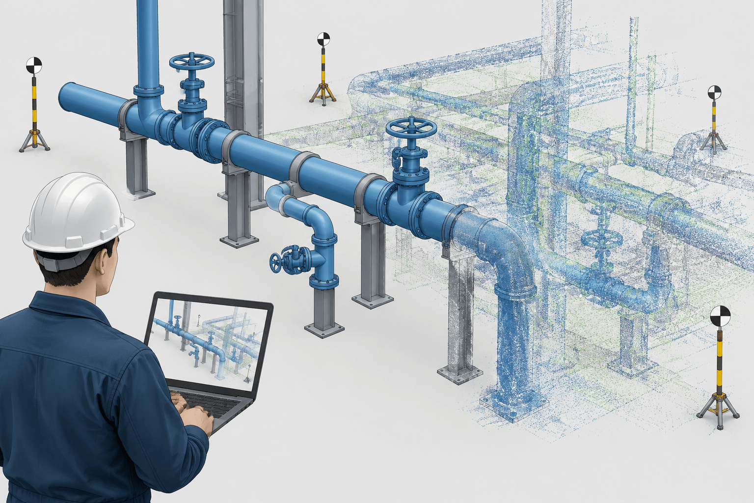
Updating piping CAD from field information requires more than matching visible geometry. The process must connect each revision to its evidence, preserve controlled component data, and clearly identify conditions that were observed, inferred, or left unverified.
This guide explains how to organize field records, classify discrepancies, update coordinated deliverables, and document verification limits. It is intended for drafters, designers, survey teams, reviewers, and project personnel responsible for maintaining dependable piping records.
As-built piping drawings are intended to describe the installed condition rather than the original design intent. Producing them is not simply a matter of copying field redlines into CAD. The drafter must determine what was actually verified, distinguish physical changes from drafting corrections, preserve useful design data, and avoid implying a level of accuracy that the field information cannot support.
A disciplined workflow turns photographs, survey points, marked-up drawings, inspection notes, and model observations into a coordinated record. It also makes uncertainty visible. This is especially important when drawings will support future tie-ins, maintenance planning, material takeoffs, or retrofit design.
Record drawing, as-built, and field-verified are not always interchangeable
Organizations use these terms differently, so the project documentation plan should define them. An as-built drawing may be understood as a representation of the completed installation, while a record drawing may describe the information assembled from contractor markups and other project records. A field-verified drawing usually indicates that specific conditions were checked at the site.
None of these labels automatically proves that every dimension, component, or hidden connection was measured. The drawing status should reflect the source and scope of verification. If only accessible routing was observed, the finished document should not imply that concealed piping or internal component details were confirmed.
Establish the verification basis before editing CAD
Before opening the model, identify what evidence is available and what the deliverable is expected to show. Typical sources include:
- Construction redlines and approved field change documents
- Survey coordinates, elevations, and control-point records
- Laser scan or point-cloud data
- Site photographs and inspection walkdown notes
- Fabrication and erection isometrics
- Equipment and valve identification observed in the field
- Test packages, weld records, and turnover documents
- Vendor drawings for installed equipment interfaces
Each source answers different questions. A point cloud can show exposed geometry but may not identify material, wall thickness, pressure class, or an obscured end connection. A photograph may confirm a valve type but provide no dependable centerline elevation. A redline may describe a routing change without recording every fitting needed to construct it.
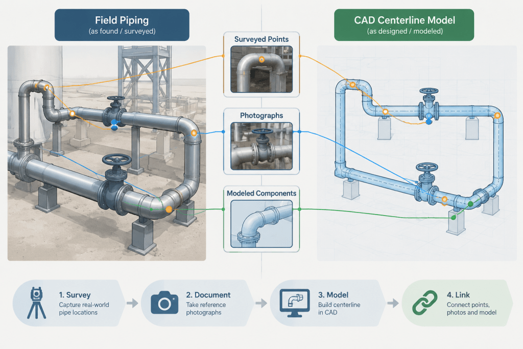
Create a verification plan that states which systems, areas, attributes, and drawing types are included. Also record the survey coordinate system, drawing units, plant datum, and any transformation applied to scan data. Without this setup, apparently precise field information can be placed incorrectly in the CAD environment.
Classify field information before making changes
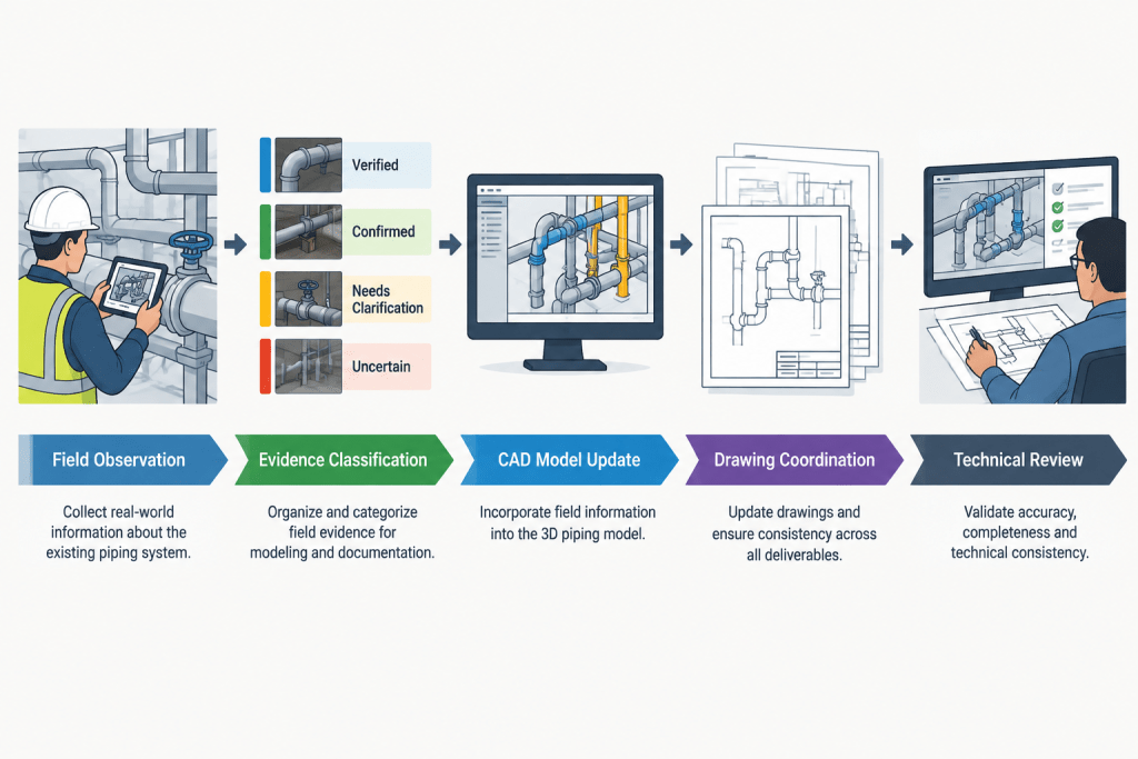
Every field observation should be classified so reviewers can understand what changed and why. A practical classification structure is shown below.
| Field information type | Typical example | CAD response |
|---|---|---|
| Physical configuration change | Rerouted pipe, relocated valve, or revised branch location | Update geometry and check affected views, dimensions, tags, and material records |
| Attribute change | Different component type or identification tag observed | Update component data only after resolving the governing documentation |
| Position refinement | Surveyed centerline differs from the construction model | Revise coordinates or elevations while retaining the verification source |
| Drafting correction | Incorrect annotation, continuation reference, or line designation | Correct the documentation without treating it as a physical field change |
| Unverified condition | Pipe continues behind equipment or below a floor | Show the known limit and add an appropriate qualification |
This separation prevents a common mistake: treating every redline as proof of an installed modification. Some redlines correct documentation that was wrong before construction, while others record genuine deviations from the design.
Use geometry sources according to what they can prove
Survey data
Surveyed points are useful for establishing centerline locations, equipment interfaces, support positions, and elevations. Confirm what each point represents before snapping CAD geometry to it. A point taken on the outside surface of insulated pipe is not automatically a pipe centerline. Likewise, a surveyed flange edge does not directly define the mating face unless the field coding or notes say so.
Point clouds
Point clouds are valuable for checking routing, congestion, access, and relationships between piping and surrounding structures. They should be registered to approved project control and checked for drift or alignment error. Model the engineering object represented by the scan rather than tracing noisy surface points literally.
Scan visibility also matters. Insulation, cladding, shadows, reflective surfaces, and crowded areas can obscure the underlying component. If a reducer, flange, or branch cannot be positively identified, retain an uncertainty note or request targeted field verification.
Photographs and walkdown notes
Photographs can confirm orientation, handle position, tag placement, support arrangement, and connection appearance. Their perspective makes them poor substitutes for controlled dimensional measurement. Organize images by area, line number, equipment item, or observation ID so another reviewer can trace a CAD change back to its evidence.
Update the model without corrupting reference data
Field verification often changes location and configuration, but it does not replace authoritative component data. Standard pipe outside diameters, fitting dimensions, flange geometry, and schedule-related properties should continue to come from the controlled project specification, approved component catalog, or verified local reference tables.
Do not distort a standard CAD component merely to match scan noise. First determine whether the difference comes from insulation, tolerance, scan registration, an incorrect catalog item, or a genuinely nonstandard component. If the installed item cannot be identified, represent it with controlled generic geometry and flag its attributes for resolution rather than assigning unsupported data.
When a route changes, review more than the visible centerline. Check:
- Fitting type and orientation
- Valve and flange locations
- Branch connectivity and flow direction
- Support relationships and structural interfaces
- Equipment nozzle connections
- Insulation and access envelopes where modeled
- Line numbers, component tags, and specification breaks
- Isometric extraction and bill-of-material behavior
Record confidence and limits of verification
A useful as-built model distinguishes confirmed facts from inferred geometry. The CAD system may support status properties, colors, layers, issue markers, or database fields for this purpose. Whatever method is selected, it should remain understandable when the model is exported or converted into drawings.
Possible verification states include directly surveyed, visually confirmed, derived from construction records, inferred between known points, and not accessible. These are descriptive categories, not universal contractual definitions. Define them in the project CAD plan and use them consistently.
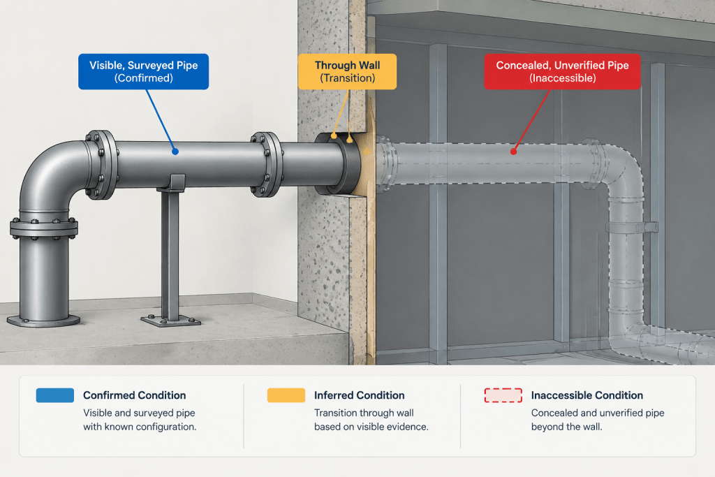
Show where verification stops. For example, a visible line may be confirmed up to a wall penetration while its concealed continuation remains based on the previous record. A note at the boundary is more useful than silently joining verified and assumed geometry.
Coordinate every affected deliverable
An as-built change rarely affects only one drawing. A relocated branch may alter the model, plan drawing, section, isometric, support schedule, line list, and tie-in register. It may also affect spool references or maintenance-access diagrams.
Use a change log that identifies the observation, source, responsible reviewer, affected documents, disposition, and closure status. This creates a traceable path from field evidence to the final deliverables. It also helps prevent the same discrepancy from being rediscovered during later projects.
Perform a structured CAD review
After incorporating field information, complete a review in stages:
- Control check: Confirm units, coordinates, datums, and scan registration.
- Connectivity check: Trace each updated line through branches, components, and continuations.
- Geometry check: Compare updated routing with survey or scan evidence without overfitting uncertain data.
- Attribute check: Verify line numbers, component types, tags, and specification assignments.
- Drawing check: Regenerate views and inspect dimensions, annotations, match lines, and hidden conditions.
- Cross-document check: Reconcile the model with isometrics, line lists, support information, and turnover records.
- Qualification check: Confirm that inaccessible or inferred areas remain clearly identified.
A second reviewer should be able to select any significant update and determine what field evidence supports it. If that connection cannot be made, the update is not fully auditable.
Common as-built drafting mistakes
- Assuming contractor redlines are complete and field-verified
- Tracing point-cloud surfaces as though they were exact pipe centerlines
- Changing component dimensions to force a visual match
- Updating plan views but leaving isometrics or schedules unchanged
- Removing design history before the revised condition is approved
- Showing concealed piping with the same confidence as surveyed piping
- Using the term as-built without defining the scope of verification
- Closing comments without recording the evidence used for resolution
A reliable final deliverable preserves context
Good as-built piping drawings do more than display the final route. They preserve the relationship between installed geometry, verified attributes, project reference data, and unresolved limitations. The objective is not to make the model look perfectly complete; it is to make the documented condition dependable and transparent.
When field evidence is classified, linked to CAD changes, and reviewed across all affected documents, future users can understand both what is shown and how confidently it is known. That makes the as-built package far more useful for maintenance, retrofit planning, and subsequent engineering work.
Practical handoff criteria for an as-built CAD package
Before release, the project team should be able to follow a significant CAD revision back to the field observation or project record that supports it. The handoff should also make clear which information remains governed by specifications, component catalogs, vendor documents, or other controlled references.
Evidence should remain traceable
File names alone rarely provide enough context. Each observation should carry an identifiable relationship to its source, affected location, review disposition, and resulting CAD change. This relationship helps later users distinguish verified installation details from inherited design information.
Qualifications should survive publication
Verification status can be lost when an intelligent model is exported to drawings or exchanged with another CAD platform. Important qualifications should therefore appear in a form that remains understandable in the issued deliverable, such as notes, status fields, layers, or clearly defined graphic conventions.
Controlled data should remain separate from field interpretation
Field evidence can justify changes to routing, location, orientation, identification, or configuration. It does not by itself establish standard component dimensions or specification properties. Those attributes should remain tied to approved project data until conflicting information has been formally resolved.
Open conditions need an explicit disposition
An inaccessible connection, unclear component, or poorly registered scan area should not be completed by assumption merely to make the drawing appear finished. The package should identify the known limit, preserve the unresolved issue, and state what additional verification is needed.
Document coordination is part of the update
A model revision is not complete if related drawings and records continue to show the previous condition. Final review should address generated views, isometrics, line information, support references, tie-in records, annotations, and other deliverables affected by the same change.
Frequently asked questions about as-built piping CAD
Does an as-built label mean every condition was field measured?
No. The label does not independently establish the scope or accuracy of verification. Project documentation should define what was checked, which evidence was used, and where verification ended.
Can a point cloud be traced directly to create pipe centerlines?
Not reliably in every case. A scan captures visible surfaces that may include insulation, cladding, obstructions, reflections, and registration effects. The drafter must interpret the engineering object and avoid treating surface noise as exact centerline geometry.
Should CAD components be stretched to match scanned geometry?
Standard components should not be distorted simply to match an uncertain scan surface. First evaluate registration, insulation, component selection, visibility, and the possibility of a nonstandard installed item. Unresolved geometry should be represented and qualified without assigning unsupported attributes.
How should concealed piping be shown?
Show the verified limit and distinguish the concealed continuation from observed geometry. If the continuation comes from an earlier drawing or construction record, preserve that source distinction rather than presenting the entire route as field-confirmed.
What is the difference between a physical change and a drafting correction?
A physical change reflects a difference in the installed configuration, such as routing or component location. A drafting correction fixes documentation that was inaccurate or inconsistent without asserting that the installation itself changed.
What makes an as-built update auditable?
An auditable update has a traceable connection among the observation, supporting evidence, review decision, CAD revision, affected documents, and closure status. Another reviewer should be able to understand why the change was made and what remains uncertain.