In piping CAD, geometry is meaningful only when its reference condition is known. This guide explains how to separate construction geometry from operating displacement, connect approved analysis data to model objects, and show thermal movement without creating duplicate material or ambiguous field dimensions.
The central question is not simply whether a line is shown cold or hot. Each drawing, model, and data exchange should identify which condition governs dimensions, which operating case produced the displayed movement, and which information is an engineering result rather than a construction instruction.
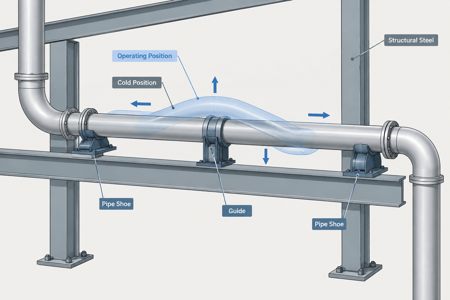
A piping model usually shows components in one geometric position, but an operating line may not remain there. Temperature changes, pressure effects, equipment movement, and support behavior can shift the pipe from its installed position. If a drawing does not identify which condition its geometry represents, designers, fabricators, support engineers, and field crews may interpret the same dimensions differently.
The distinction between cold position and hot position is therefore more than analysis terminology. It affects equipment nozzle connections, support placement, guide gaps, spring support settings, rack coordination, and field installation instructions. CAD documents should communicate these conditions without turning the model into an unreadable collection of overlapping pipe runs.
What cold position and hot position mean
The cold position generally describes the piping geometry when the system is not at its operating temperature. Depending on project terminology, it may refer to the fabricated, erected, or initial installed condition. It is commonly the physical position used for construction dimensions and spool fabrication.
The hot position describes the expected displaced geometry under a defined operating condition. The term does not necessarily mean that every system carries a high-temperature fluid. A refrigerated or cryogenic line can also move significantly, even though contraction rather than heating drives the displacement. For that reason, operating position is often the more precise general term.
These labels should not be treated as universal without checking project definitions. A line may have several analyzed conditions, including startup, normal operation, shutdown, upset, or alternative equipment cases. There may be more than one operating position.
Related position terms
| Term | Typical meaning | CAD implication |
|---|---|---|
| Design or nominal position | The routing basis established by layout coordinates and elevations | May be the primary model centerline, but it is not automatically the field installation position |
| Installed position | The intended field position before the specified operating movement occurs | Usually the condition needed for construction dimensions |
| Cold position | The nonoperating reference state used by the project or analysis | Often coincides with installed geometry, but that relationship should be confirmed |
| Operating or hot position | The displaced state for a particular operating case | Usually communicated with movement data, envelopes, or supplemental graphics |
| Preset position | An intentional installation offset used to account for later movement | Requires explicit direction, reference point, condition, and field instruction |
Why the primary CAD model normally uses one position
Modeling both cold and operating geometry as equal-status pipe runs can create duplicate components, false clashes, and unreliable material quantities. It may also leave downstream users unsure which line controls fabrication.
A practical approach is to choose one governing geometric state for the main piping model and declare it in the project CAD basis. For many projects, this is the installed or cold position because spools and supports must be located before operation. Expected movement can then be represented with controlled supplemental information.
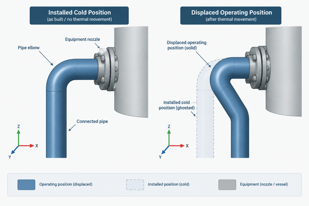
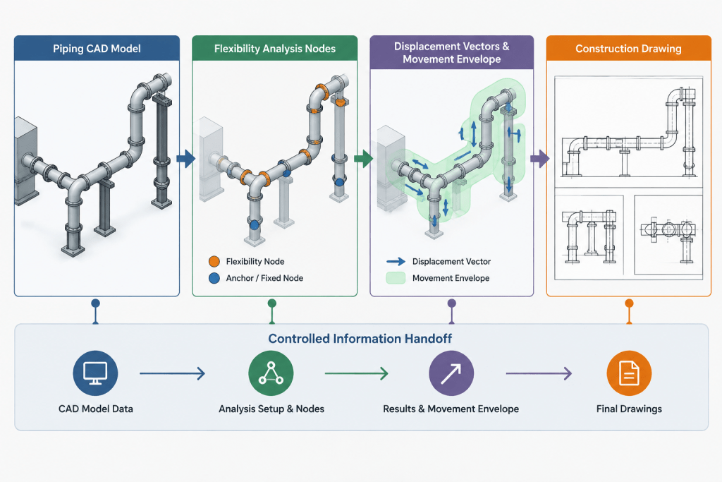
The selected model basis should be consistent across piping plans, isometrics, support documents, equipment interfaces, and model exports. If an analysis model uses a different reference state, the handoff notes should explain the transformation rather than assuming that coordinates are directly interchangeable.
Displacement is a vector, not just a distance
A statement such as “the line moves toward the rack” is not enough for detailed coordination. Movement has direction and magnitude in the project coordinate system. It may include longitudinal, lateral, and vertical components, as well as rotations at equipment nozzles or branch connections.
CAD teams should receive displacement data tied to identifiable nodes, supports, nozzles, or other agreed reference points. A useful movement record identifies:
- The line or system associated with the result
- The analyzed operating case
- The node, support, or nozzle identifier
- The coordinate convention and positive directions
- Translational movement components
- Any relevant rotation information
- The revision and status of the analysis input
Movement arrows in a drawing are helpful visual cues, but they should not replace traceable displacement data. An arrow without a defined reference condition can be mistaken for flow direction, installation direction, or the orientation of a support slot.
Ways to show operating movement in CAD
Movement arrows and labeled vectors
For localized review, show an arrow from the cold reference point toward the operating position. Label the operating case and connect the note to a specific nozzle, support, or analysis node. Use a graphics convention distinct from process flow arrows.
Ghosted operating geometry
A simplified phantom or ghosted outline can illustrate where a pipe segment, valve operator, or equipment connection is expected to move. Keep this geometry on a dedicated nonmaterial layer or in a separate review file so it cannot be counted as installed piping.
Ghosted geometry should be limited to areas where movement affects access, steel, adjacent piping, or other interfaces. Duplicating an entire system often produces more confusion than value.
Movement envelopes
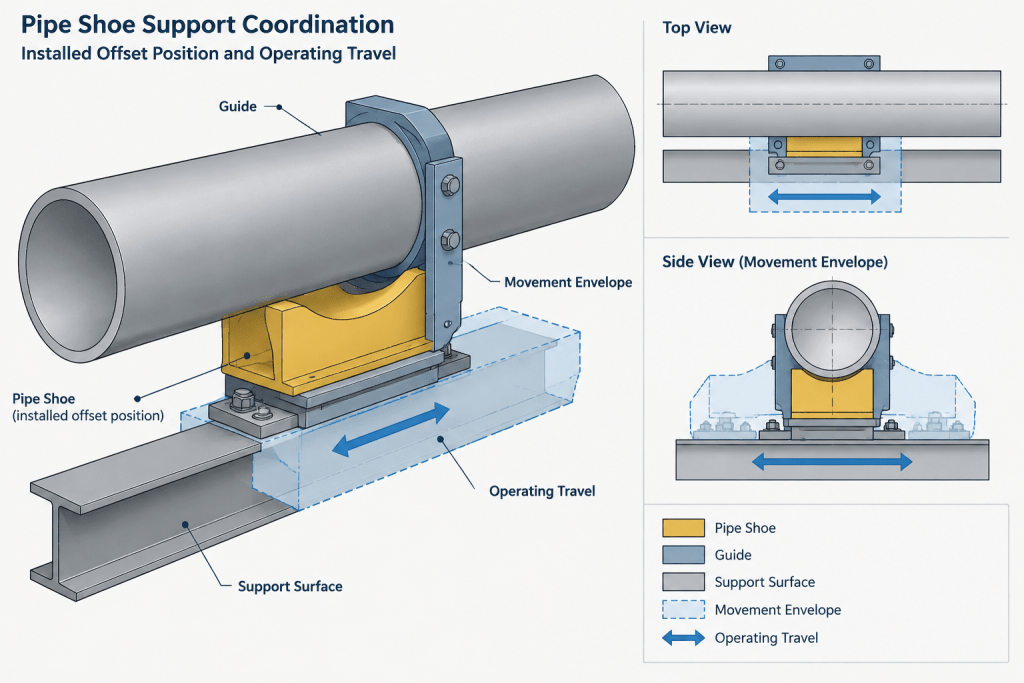
An envelope communicates the region occupied as the line moves between relevant conditions. It is useful for checking nearby structural members, cable tray, ducts, platforms, and insulation clearance. An envelope is not the same as the pipe outside diameter; the basis may need to include insulation, attachments, or uncertainty allowances defined by the responsible disciplines.
Support travel indicators
Supports may need arrows, slot directions, travel ranges, or cold and operating reference marks. The drawing should distinguish pipe movement from support component travel. At a sliding support, for example, pipe displacement relative to steel is the key interface. At a spring support, the support specialist may also need the intended installation setting and operating position.
Preset and cold-spring information requires special control
Preset geometry intentionally places part of a system away from an otherwise expected neutral position so that operation moves it toward another condition. This concept may appear at pipe supports, spring assemblies, equipment connections, or selected spool interfaces.
Do not infer a preset simply by shifting model geometry. An unexplained offset can be “corrected” during coordination or fabrication because it looks like an error. Preset instructions should be approved by the responsible engineering discipline and documented as construction requirements.
A clear preset note should identify:
- The exact point or component to be offset
- The reference point from which the offset is measured
- The direction using the project coordinate convention
- The condition in which the measurement applies
- Whether temporary restraints or erection steps are involved
- The document or calculation that controls the instruction
CAD personnel should not calculate or introduce cold spring independently. Its effects involve system forces, equipment interfaces, installation sequence, and analysis assumptions.
Support coordination between cold and operating states
A support that looks centered beneath the pipe in the model may not remain centered during operation. Conversely, a shoe or clamp that appears offset in the installed condition may be intentionally positioned to accommodate travel.
Review support interfaces by asking four separate questions:
- Where is the pipe installed? This controls field location and construction dimensions.
- Where does the pipe move? This controls travel direction and potential interference.
- Which support surfaces move relative to each other? This affects sliding plates, guides, slots, and stops.
- What position does the support drawing depict? A support detail may show a centered conceptual arrangement rather than the required installed offset.
The piping model, support schedule, support detail, and analysis output should use the same support identifier. Without that common key, even accurate movement data can be applied to the wrong location.
Equipment nozzles and connected piping
Equipment nozzles may move with the equipment shell, casing, skid, or foundation system. The operating displacement of a nozzle is therefore not always generated by pipe expansion alone. CAD coordination should preserve the distinction between equipment movement and pipe movement relative to the nozzle.
At each critical interface, verify which coordinates represent the equipment installation condition and which movements belong to an operating case. Avoid shifting a nozzle in the piping model unless the model state and ownership of that change are clearly established. Otherwise, the equipment and piping teams may both apply the same displacement, creating a double offset.
A practical CAD review workflow
- Confirm the model basis. Record whether the primary geometry represents the installed, cold, nominal, or another defined condition.
- Identify movement-sensitive interfaces. Include equipment nozzles, guides, line stops, spring supports, rack boundaries, penetrations, and close clearances.
- Import or transcribe approved displacement data. Check node identifiers, coordinate axes, units, operating cases, and revision status.
- Add controlled movement graphics. Use dedicated layers, object properties, or review models for arrows, envelopes, and ghosted geometry.
- Check both endpoint and travel path. A pipe may clear an object at the cold and operating positions but interfere while moving between them.
- Reconcile support documents. Confirm travel direction, installed offset, attachment location, and component orientation.
- Issue explicit construction information. Put required installed dimensions and approved preset instructions on the documents used in the field.
- Remove ambiguity before release. Ensure that duplicate geometry cannot enter bills of material, spool extraction, or fabrication exports.
Common documentation mistakes
- Calling the model “hot” or “cold” without defining the term
- Showing two pipe positions with the same line style and layer
- Using analysis node coordinates as construction coordinates without checking the reference state
- Applying equipment movement once in the equipment model and again in the piping model
- Centering every shoe or guide in the cold model despite expected one-direction travel
- Using movement arrows that can be confused with flow arrows
- Checking only the final operating position rather than the swept movement path
- Adding field preset notes without engineering approval or a traceable basis
What the final drawing should communicate
A well-coordinated drawing does not need to display every analysis result. It needs to tell each user which geometry controls their work, where movement affects an interface, and where special installation action is required.
The primary dimensions should remain tied to the declared construction state. Operating positions can be communicated selectively through vectors, envelopes, supplemental views, and support annotations. This separation keeps fabrication geometry dependable while still making thermal movement visible to reviewers.
Cold position versus hot position is ultimately a configuration-control issue. When model state, analysis case, coordinates, and construction instructions are clearly separated, CAD becomes a reliable bridge between layout, flexibility analysis, support design, and field installation.
A documentation hierarchy for model, analysis, and construction data
Clear thermal-movement documentation separates information by purpose instead of placing every condition into the primary piping geometry. This helps each discipline understand what controls its work.
- Governing model geometry: The declared reference condition used for layout, dimensions, component identity, and material extraction.
- Analysis overlay: Approved vectors, ghosted geometry, envelopes, and case-specific movement data used for coordination and review.
- Construction instruction: Explicit requirements for installed offsets, support settings, temporary restraints, or approved presets that field personnel must apply.
An analysis overlay should not silently become fabrication geometry, and a construction requirement should not be inferred from a graphical offset alone. When information moves between these categories, the responsible discipline should approve the change and the document revision should preserve its traceable basis.
Release checks for movement-sensitive CAD documents
Before issuing a model or drawing, reviewers can use the following questions as a focused release gate:
- Does the document identify the condition represented by the primary geometry?
- Is every displayed movement tied to a named operating case and an identifiable point?
- Are coordinate directions and movement-arrow conventions clear?
- Can ghosted geometry or movement envelopes be excluded from material and fabrication outputs?
- Do piping, equipment, support, and analysis records use consistent identifiers?
- Are required field offsets presented as approved instructions rather than implied by appearance?
- Has the movement path been reviewed where nearby objects or support surfaces may interfere?
- Do revision notes reveal when movement data, model geometry, or interface assumptions changed?
Managing revisions without losing the reference state
Thermal-movement graphics can become misleading when the piping route changes but an older analysis overlay remains visible. Treat movement objects as controlled data associated with a specific model revision, analysis status, and operating case. If the governing geometry changes, affected vectors, envelopes, support travel indicators, and preset notes should be revalidated rather than carried forward automatically.
This separation also improves review quality. Layout reviewers can see the installed configuration, support specialists can identify relative travel, and field users can find actionable requirements without interpreting analysis graphics as construction dimensions.
Frequently asked questions
Is the cold position always the installed position?
No. The terms often describe the same geometry, but project definitions may distinguish nominal, fabricated, erected, installed, and analysis reference conditions. The CAD basis should state the relationship explicitly.
Does hot position apply only to heated piping?
No. Hot position is commonly used for an operating displacement state, but operating position is the broader term. Refrigerated and cryogenic systems may move through contraction rather than heating.
Should the operating position be modeled as a duplicate pipe run?
Usually the primary model should retain a single declared geometric state. Operating movement can be communicated with controlled overlays, vectors, envelopes, or supplemental views so duplicate objects do not affect clash results, material quantities, or fabrication exports.
What is the difference between a movement arrow and a flow arrow?
A movement arrow represents displacement between defined conditions, while a flow arrow indicates process direction. Distinct graphics, labels, and layer conventions help prevent the two from being confused.
Can a CAD designer add a preset based on expected movement?
A preset should not be introduced independently by CAD personnel. It requires approval from the responsible engineering discipline because it can affect system forces, equipment interfaces, support behavior, and installation sequence.
Why can a pipe clear nearby objects at both endpoint positions but still clash?
The route between the cold and operating positions may sweep through space that neither endpoint occupies. Movement-sensitive coordination should therefore consider the travel path or envelope, not only the final positions.