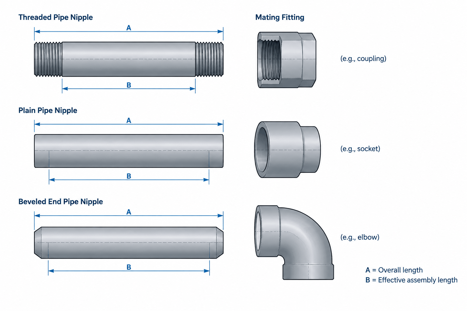
Pipe nipple lengths in CAD must be interpreted according to the component definition and connection method. The length assigned to the standalone item may not equal the axial space it occupies after threaded engagement, socket insertion, or end preparation is considered.
This guide explains how to distinguish purchased length, fabrication length, and effective assembly geometry without treating a catalog dimension as an automatic fitting-to-fitting gap. It also provides a practical basis for coordinating CAD objects, drawing dimensions, and bills of material.
A pipe nipple looks simple: a short piece of pipe with an end connection at each end. In CAD and fabrication documentation, however, its length can be misunderstood. A catalog length may describe the overall finished component, while a modeler may accidentally treat it as the visible distance between connected fittings. Thread engagement, socket insertion, end preparation, and manufacturing method can all change the resulting assembly geometry.
The safest workflow is to separate three questions: What component is being purchased or fabricated? What dimension defines that component? What assembled distance will remain after its ends enter or join adjacent components? Numeric pipe and nipple tables should remain the source for verified dimensions. CAD geometry should interpret those values rather than replace them with assumptions.
What Is a Pipe Nipple?
A pipe nipple is a short section of pipe furnished with prepared ends for connection to other piping components. Common configurations include threaded ends, plain ends, beveled ends, and combinations of different end preparations. Some nipples are standard purchased items, while others are cut and prepared by a fabricator from specified pipe material.
The word nipple does not by itself define the exact length basis, wall schedule, material, or end preparation. Those attributes must come from the applicable piping specification, purchase description, project catalog, or verified dimensional reference.
Key Length Terms That Should Not Be Confused
| Term | Practical meaning | CAD consequence |
|---|---|---|
| Overall length | The finished distance from one physical end of the nipple to the other | Defines the standalone component envelope before assembly |
| End-to-end length | A length measured between the two ends; often equivalent to overall length, subject to the product definition | Should not automatically be treated as fitting-to-fitting separation |
| Cut length | The length of pipe stock cut before or during end preparation | May differ from the finished or theoretical assembly dimension |
| Engagement length | The portion of a threaded end that enters a mating threaded component | Reduces the exposed length between adjacent components |
| Socket insertion | The portion of pipe or nipple inserted into a socket-type component | Must be accounted for when calculating the assembled face-to-face distance |
| Effective assembly length | The axial distance contributed by the nipple after its connections are assembled | Controls the location of adjacent fittings, valves, or equipment interfaces |
These terms may overlap in informal conversation, but they serve different purposes. A bill of materials typically describes the physical item. A layout model needs the installed geometry. A fabrication document may also need stock cut information and end-preparation instructions.
Why Overall Length Is Not Always the Installed Gap
Consider a threaded nipple connecting two threaded fittings. The nipple’s overall length includes both threaded ends. During assembly, part of each end enters its mating fitting. The visible or external distance between the fittings is therefore less than the nipple’s standalone overall length.
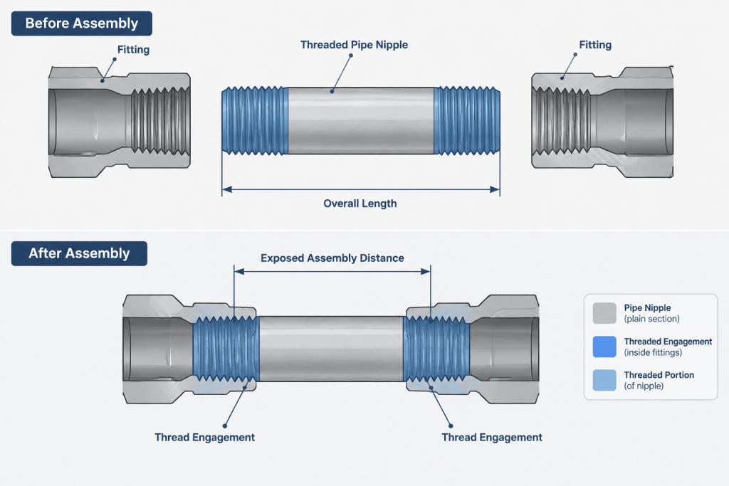
A conceptual relationship is:
Effective assembly length = nipple overall length − engagement at end A − engagement at end B
This is a geometry relationship, not a substitute for verified engagement data. Actual makeup can depend on thread form, component tolerances, sealing method, assembly practice, and the mating fitting. A CAD model should not imply that a tapered threaded joint stops at a universally fixed point unless the project has established an approved modeling rule.
Socket-connected nipples create a similar issue. The pipe enters each socket, so the distance between component faces is not equal to the nipple’s full end-to-end length. For welded plain-end or beveled-end nipples, the controlling dimensions instead involve weld-end locations, specified joint details, and fabrication cut-length rules.
Close Nipples Need Special Treatment
A close nipple is a very short threaded nipple in which the threaded regions occupy most or all of the available length. It may have little or no practical unthreaded wrenching area between the ends. That makes it different from a longer nipple shown as a generic pipe cylinder with short threads added at each end.
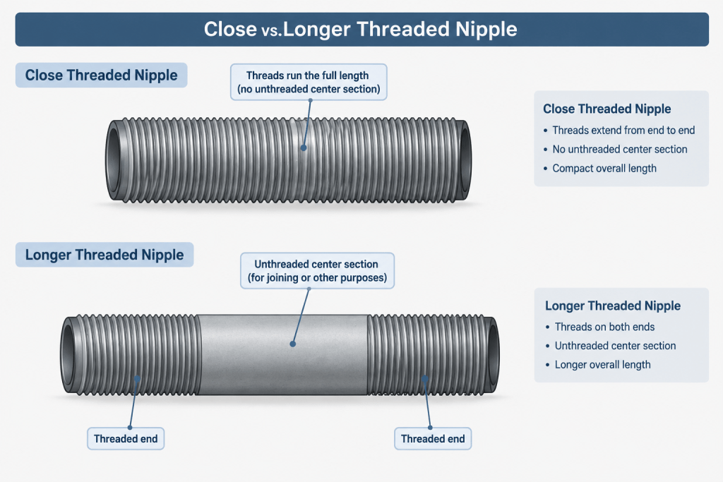
Do not create a close nipple by selecting an arbitrary short length in CAD. Its geometry and availability depend on pipe size, thread configuration, wall selection, material, and the applicable product definition. Use the site’s verified reference data or an approved manufacturer source for the item being specified.
Close nipples also create practical review questions:
- Can the joint be assembled in the planned sequence?
- Is there enough accessible surface for the intended installation method?
- Will tightening one end loosen or prevent makeup at the other?
- Can the connected components be removed without disturbing surrounding piping?
- Does the project specification permit the selected connection arrangement?
These are coordination issues rather than conclusions that can be drawn from a nominal CAD cylinder alone.
Modeling Strategies for Pipe Nipples
Use a catalog component when identity matters
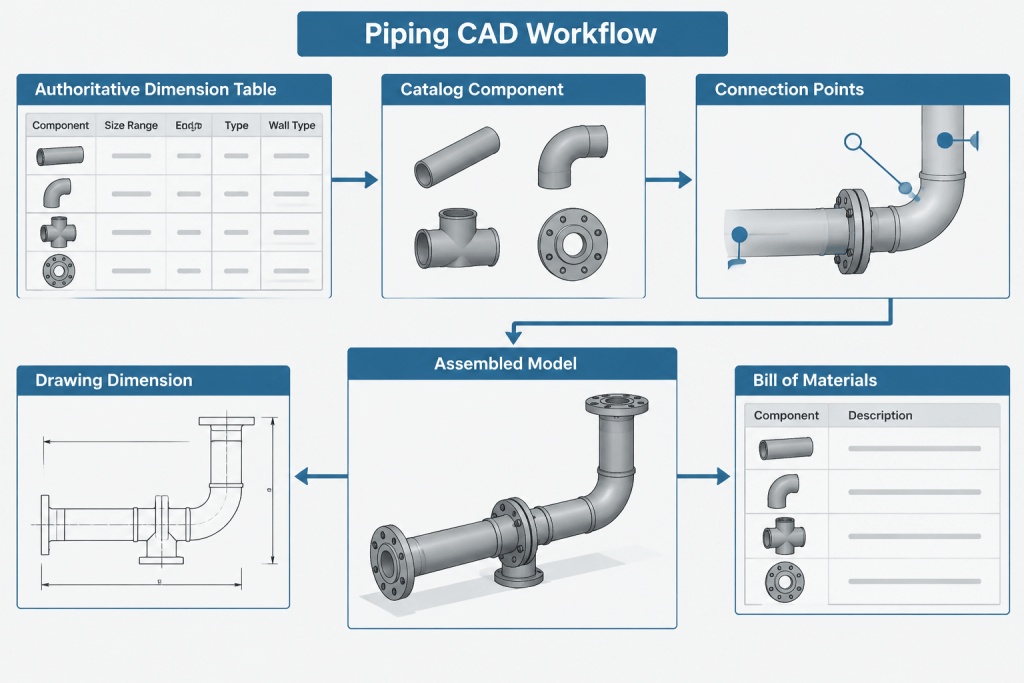
A catalog-driven object is appropriate when the nipple must appear as a distinct purchased item in the bill of materials. Its data should include size, schedule or wall designation, material specification, end preparation, and the approved length description. Keep dimensional values linked to authoritative project or database records where the software permits.
Use pipe geometry when it is fabricated from stock
If the nipple is cut from project pipe and prepared by the fabricator, it may be modeled as a short pipe segment rather than a stocked specialty item. The drawing still needs to communicate the required ends and finished length basis. The BOM description should make clear whether the item is loose pipe, a prepared nipple, or part of a fabricated spool.
Separate symbolic and physical representations
On a small-scale plan or isometric, a short nipple may be represented symbolically because its exact thread geometry would be unreadable. In a fabrication model, connection points and component extents may need greater precision. Both representations can be valid if they use the same underlying component identity and do not produce conflicting dimensions.
Do not model detailed threads unless they add value
Helical thread geometry increases model complexity and rarely improves piping coordination. A simplified threaded zone, connection point, or metadata-based end type is usually more useful. Detailed threads may be appropriate for a focused manufacturing detail, but they should not be required merely to calculate layout geometry.
A Reliable CAD and Detailing Workflow
- Identify the connection at each end. Confirm whether each end is threaded, socket-connected, plain, beveled, or another approved preparation.
- Determine the item source. Establish whether the nipple is a standard purchased component or fabricated from pipe stock.
- Read the length definition. Verify whether the listed dimension is overall, end-to-end, cut, or another defined basis.
- Use verified dimensional data. Obtain component dimensions from the project’s controlled catalog or the site’s reference tables rather than estimating from graphics.
- Apply the connection model. Use approved engagement, insertion, weld-end, or connection-point logic for the adjacent components.
- Check the resulting assembly. Confirm that fitting faces, valve ends, equipment connections, and support locations land where intended.
- Coordinate the BOM description. Ensure the reported item matches what the model represents and what procurement or fabrication is expected to supply.
- Review constructability. Consider assembly sequence, tool access, disassembly, and whether nearby components can rotate or move as required.
How to Dimension a Nipple on a Drawing
Dimension the feature that the drawing recipient must control. A purchasing description may need the nipple’s finished overall length. A spool drawing may need weld-to-weld or connection-point dimensions. An arrangement drawing may need the location of fitting centerlines or equipment faces rather than the nipple length itself.
Avoid placing several dimensions on the same view if they control the same axial chain in different ways. For example, separately controlling the nipple overall length, the gap between fittings, and the total assembly length can create an overconstrained drawing if thread engagement is not fixed. Mark reference dimensions clearly when they are provided only for checking.
Notes should state the dimension basis when it could be misread. Useful wording identifies the physical endpoints, such as finished end to finished end or theoretical connection point to theoretical connection point. The note should not attempt to redefine a standardized product; it should clarify how the drawing uses the selected data.
Common Errors to Catch During Review
- Using nominal pipe size as though it were a physical nipple length or outside diameter.
- Placing connected fitting faces one nipple overall length apart without accounting for engagement or insertion.
- Calling out a close nipple while modeling a longer nipple with an unthreaded center section.
- Reporting a fabricated pipe segment as a purchased nipple, or the reverse.
- Leaving end preparation out of the BOM description.
- Using a generic library component whose schedule, material, or end type conflicts with the piping specification.
- Adding dimensions that imply exact threaded makeup when the project model uses a nominal connection convention.
- Ignoring the installation sequence for a nipple trapped between components that cannot rotate.
Final Review Principle
A pipe nipple has both a physical item length and an installed geometric effect. Those values are not automatically identical. Reliable CAD documentation preserves the distinction among overall length, cut length, engagement, insertion, and effective assembly length. Use authoritative dimensional tables for the component itself, then apply a documented connection convention to place it correctly in the piping assembly.
Match the CAD Dimension to Its Intended Use
Before accepting a nipple dimension, identify what the value is intended to control. Procurement needs an unambiguous component description, fabrication needs the correct finished or cut-length basis, and piping layout needs reliable connection locations. A single field labeled length may not adequately serve all of these purposes.
A useful CAD data structure keeps the verified component length separate from calculated assembly geometry. The component record can describe what is supplied, while connection data controls how much of each end enters or joins the adjacent component. This prevents a layout adjustment from silently changing the item reported in the bill of material.
Apply a Clear Data Priority
When the model, catalog, drawing, and specification appear to disagree, do not resolve the conflict by measuring displayed geometry. Review the controlled component definition, the stated dimension basis, the end preparation, and the connection convention used by the project. Escalate unresolved differences rather than editing a library item to make the assembly appear correct.
Check More Than the Nipple Object
The connected fittings also affect the result. Their connection points, socket geometry, threaded-end conventions, and model origins must agree with the nipple logic. A correctly defined nipple can still produce an incorrect assembly if the mating components use a different insertion or engagement convention.
Record Assumptions That Affect Deliverables
- State whether the nipple is purchased as a distinct component or fabricated from pipe stock.
- Identify the end preparation at each end.
- Define whether the reported length is a physical component length or an effective layout dimension.
- Confirm that the drawing and bill of material use the same component identity.
- Document any nominal CAD connection convention that does not represent exact field makeup.
Pipe Nipple Length FAQ
Is nipple end-to-end length the same as the gap between fittings?
Not necessarily. End-to-end length generally describes the standalone nipple, while the installed gap depends on how its ends engage, insert into, or join the mating components.
Should thread engagement be modeled as an exact fixed distance?
Only when a controlled project rule or verified component definition establishes that modeling basis. Actual threaded makeup can vary, so CAD should not imply unsupported precision.
How should a close nipple appear in CAD?
It should be represented as the specified close-nipple component rather than as an arbitrarily shortened generic pipe segment. Simplified geometry is acceptable when the component identity, end type, and approved length definition remain clear.
Can a nipple be modeled as ordinary pipe?
It may be appropriate when the item is fabricated from project pipe stock. The model and documentation must still identify the required end preparations and distinguish stock cut length from finished or installed geometry.
Which nipple dimension belongs on a spool drawing?
Use the dimension needed to control fabrication and assembly. Depending on the connection, that may be a finished component length, a weld-related dimension, or a connection-point dimension. Avoid redundant dimensions that impose conflicting control.
Why can the CAD model and bill of material disagree?
The model may use effective assembly geometry while the bill of material reports the physical purchased item. Disagreement occurs when these separate purposes are stored in one undifferentiated length field or when the end-connection logic is incomplete.
Do detailed thread forms need to be included in a piping model?
Usually not for layout coordination. A simplified threaded region, connection point, and accurate component metadata normally communicate the necessary design intent with less model complexity.