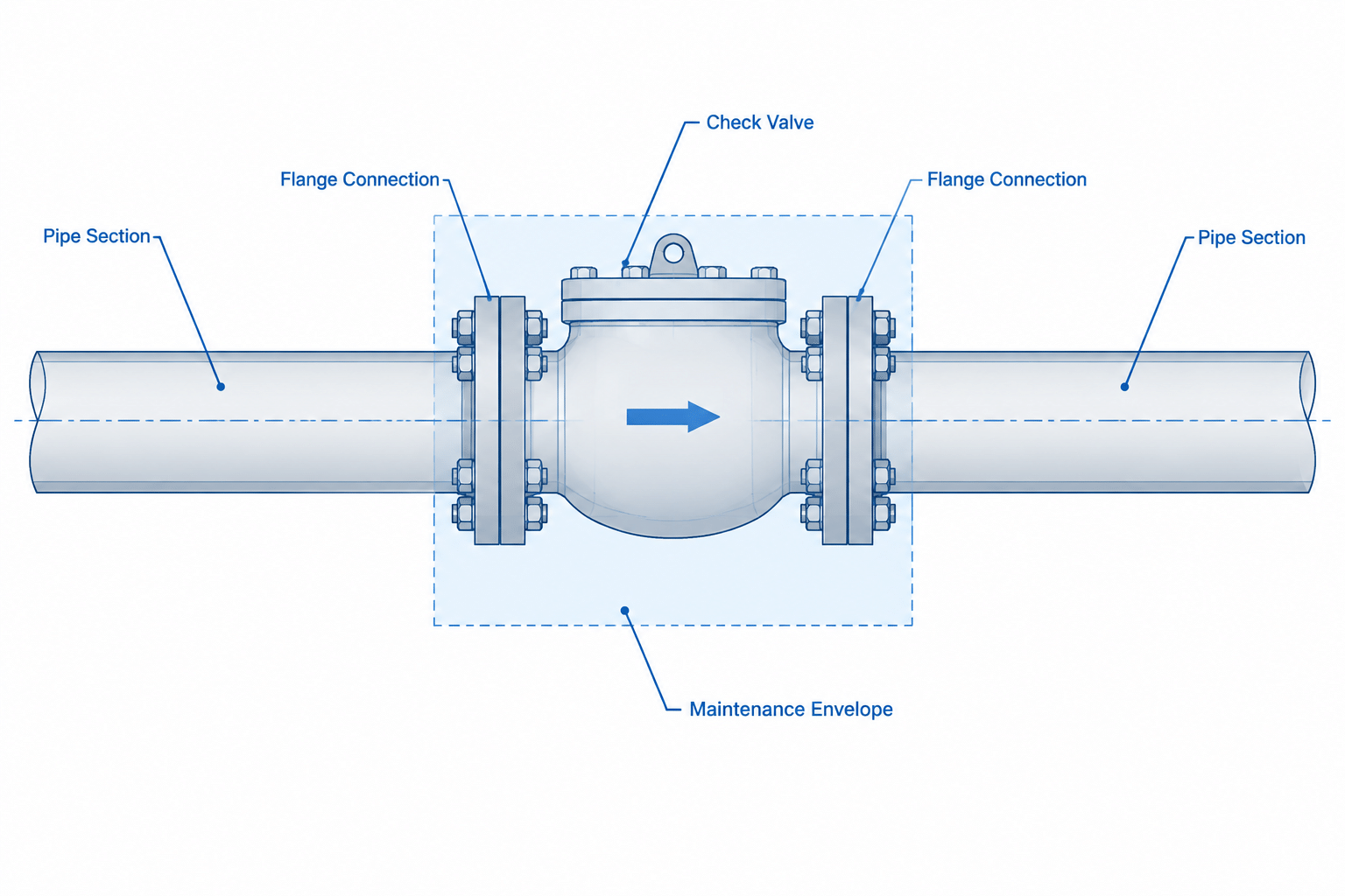
Check valve modeling requires more than placing a valve body in a pipe run. The selected CAD component must communicate direction, connection arrangement, permitted orientation, dimensional status, and access needs without implying that unverified geometry is approved for construction.
This guide explains how common check valve mechanisms affect piping layout and how to coordinate the model with process documents, valve data, isometrics, material reporting, and maintenance planning.
A check valve allows flow in the intended direction while resisting reverse flow. That simple function can hide important differences in geometry, installation limits, dynamic behavior, and maintenance requirements. A generic valve symbol may be adequate during early design, but it is rarely enough for a coordinated piping model or fabrication drawing.
When representing a check valve in CAD, designers must account for more than nominal pipe size and end connection. The valve type, flow arrow, permitted orientation, face-to-face dimension, internal movement, cover access, and surrounding piping can all affect whether the installed assembly will function and remain maintainable.
Why check valve type matters in a piping model
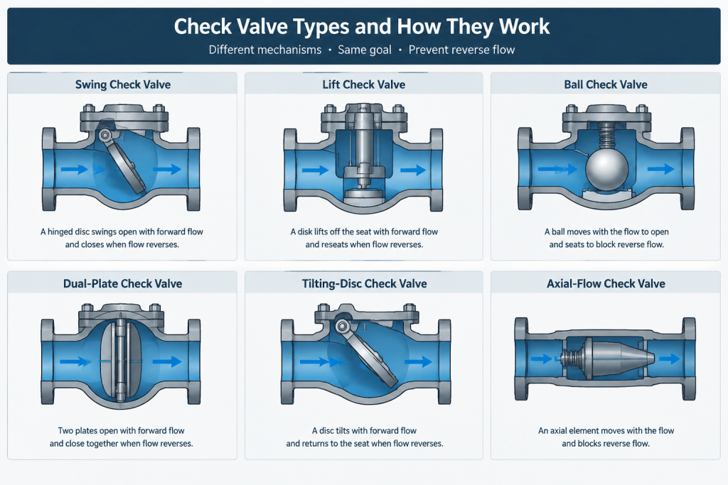
Check valves are available with different closure mechanisms. A swing disc, guided piston, ball, pair of spring-loaded plates, or axially moving disc does not respond to flow in the same way. These internal differences can also change the valve body’s external proportions and the space required for inspection.
CAD should not be used to infer performance from appearance. A compact body does not automatically mean that the valve is appropriate for every orientation, and a conventional body shape does not confirm its internal design. Selection should follow the piping specification, process requirements, approved valve data, and manufacturer documentation.
Common check valve types
| Type | General closure arrangement | CAD and layout concerns |
|---|---|---|
| Swing check | A hinged disc swings away from the seat as flow passes through the body. | Show the correct flow direction and allow access to the body cover or hinge area. Installation orientation may be restricted. |
| Lift or piston check | A guided closure element lifts from the seat and returns when forward flow decreases. | Confirm permitted pipe orientation, body direction, cover access, and pressure-drop implications with project data. |
| Ball check | A ball moves away from and back toward a seat within the valve body. | Do not assume orientation from the external body alone. Verify the internal path and approved mounting position. |
| Dual-plate check | Two plates rotate around a central support, commonly with spring assistance. | The short body may fit between flanges, but bolt compatibility, plate clearance, flow direction, and removal space still require checking. |
| Tilting-disc check | A disc pivots around an offset axis rather than swinging from a simple top hinge. | Use verified envelope and connection dimensions. Body asymmetry may make reversal errors less obvious in simplified models. |
| Nozzle or axial-flow check | A guided disc moves generally along the flow axis, often with spring assistance. | Confirm body length, flow direction, connection geometry, and vendor-specific external details before issuing drawings. |
These descriptions identify broad families rather than complete purchasing specifications. Products within the same family can differ substantially, so a representative library component should not replace verified project data.
Flow direction is a controlled property
A check valve is directional. Reversing it can prevent forward flow, defeat reverse-flow protection, or produce unintended operating behavior. The model therefore needs an unambiguous relationship between the valve ports and the process flow direction.
A reliable CAD component should include:
- An inlet port and an outlet port rather than two interchangeable connection points.
- A visible or reportable flow-direction property.
- A body arrow or directional marker where appropriate for the drawing scale.
- A consistent relationship between the 3D component, isometric symbol, P&ID information, and bill of materials.
Do not rely only on the modeled body shape. Symmetrical wafer-style bodies can look identical when rotated end for end, and simplified isometric symbols may not show enough detail to expose an error. A model check should compare the valve direction with the line’s intended process flow.
Installation orientation must be verified
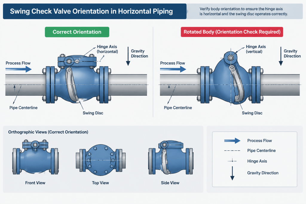
Some check valve mechanisms depend on gravity, while others use springs or guided motion. Consequently, an arrangement accepted for one valve design may be prohibited or limited for another. Even valves sold under the same broad type name may have different orientation instructions.
Before placing the final component, verify whether the selected valve is permitted in:
- Horizontal piping.
- Vertical upward flow.
- Vertical downward flow.
- Inclined piping.
For a swing check, the location of the hinge and cover can be critical. Rotating the body around the pipe axis merely to make the model look tidy may change how gravity acts on the disc. For guided or spring-assisted designs, greater orientation flexibility may be available, but it should never be assumed without documentation.
If final vendor information is unavailable, label the component as preliminary and record the unresolved orientation requirement. This is safer than allowing a generic model to appear fully verified.
End connections and dimensional control
Check valves may use flanged, wafer, lugged, threaded, socket-weld, butt-weld, or other specified end arrangements. The connection style determines how the valve participates in the piping assembly and which dimensions control adjacent pipe.
Flanged valves
Use the verified face-to-face dimension and correct flange data. Include gasket positions in joint-stack reviews and check that adjacent bolting can be installed and removed. A flanged body may also require enough separation for maintenance after bolts are withdrawn.
Wafer-style valves
A wafer valve is clamped between mating flanges rather than carrying a conventional flange at each end. Model its installed width and actual centering arrangement. Check that the selected valve is compatible with the flange facing, gasket arrangement, bore, and bolting configuration specified for the line.
Welded-end valves
For butt-weld or socket-weld ends, distinguish the valve’s overall or end-to-end dimension from pipe cut length. Weld preparation, insertion, and fabrication allowances must follow the applicable project documentation. Replacing a welded valve can also require a different field strategy than replacing a bolted valve.
Threaded valves
Threaded check valves need verified thread type, engagement assumptions, and assembly access. A valve trapped between rigid threaded runs may be difficult to install or remove even when its modeled length is correct.
Model the maintenance path, not just the operating envelope
A check valve has no handwheel, but it can still need significant maintenance space. Covers may be lifted, hinge pins withdrawn, internal cartridges removed, or the entire body extracted from between flanges. Nearby steel, cable tray, insulation, or another pipe can obstruct these tasks without creating a conventional hard clash.
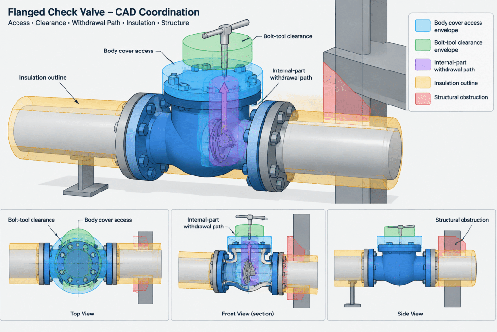
Useful maintenance checks include:
- Clearance above or beside a bolted cover.
- Space for tools around cover fasteners and flange bolts.
- A withdrawal path for internal parts where applicable.
- Room to spread or move connected piping for valve removal.
- Handling access for the valve or removable cover.
- Clearance after insulation and removable insulation covers are added.
Keep maintenance envelopes separate from the physical valve body in CAD. They can be placed on a dedicated layer or assigned a non-material model category so they support coordination without appearing in the bill of materials.
Check valve placement near equipment
Check valves are frequently located near pumps, compressors, vertical risers, and branch connections. Their placement must balance process function with constructability and access. A valve placed close to an equipment nozzle may appear efficient but could interfere with nozzle bolting, equipment maintenance, reducers, instruments, or pipe supports.
Flow conditions can also influence selection and location. Disturbed or pulsating flow may cause unstable closure behavior in some applications. The required straight-run arrangement, if any, should come from the engineering basis or verified manufacturer guidance rather than a generic CAD rule.
Check that the valve’s weight and dynamic effects are considered by the piping and support disciplines. The CAD designer should not assign support loads without engineering input, but the model must provide accurate component locations and enough space for the selected support arrangement.
Recommended CAD workflow
- Read the line data. Confirm line number, nominal size, material class, end connection, and intended flow.
- Identify the required check valve family. Do not substitute one mechanism for another because the library geometry is convenient.
- Obtain verified dimensions. Use approved project or manufacturer information for the specific valve being modeled.
- Place directional ports correctly. Align the inlet with upstream piping and the outlet with downstream piping.
- Set the approved orientation. Check body rotation as well as whether the line is horizontal, vertical, or inclined.
- Connect the actual end type. Include the correct flange, gasket, weld, thread, or wafer assembly logic.
- Add access envelopes. Represent cover removal, internal-part withdrawal, bolting access, and valve extraction.
- Review adjacent components. Check equipment nozzles, reducers, supports, instruments, insulation, and structural obstructions.
- Reconcile documents. Compare the model, P&ID, line list, valve data, isometric, and bill of materials.
Common modeling errors
- Installing the check valve opposite to process flow.
- Using a generic valve body with the wrong end-to-end dimension.
- Rotating a gravity-sensitive valve into an unapproved position.
- Treating a wafer valve as if it had integral flanged ends.
- Leaving no access for a top cover, hinge pin, or removable cartridge.
- Showing the correct 3D orientation but an inconsistent isometric or P&ID direction.
- Replacing the specified type with a visually similar library component.
- Failing to update adjoining pipe lengths after vendor dimensions change.
Final review principle
A check valve should be treated as a directional mechanical component, not as a generic interruption in a pipe run. Good CAD documentation connects process intent to physical installation by showing the correct valve type, flow direction, orientation, connection arrangement, dimensional envelope, and maintenance needs. Final suitability still depends on the applicable piping specification, engineering review, and verified product data.
Separate geometric accuracy from functional verification
A check valve model can be dimensionally accurate while still being functionally incorrect. Correct body length and connection geometry do not confirm that the valve is facing the intended flow, mounted in an approved position, or suitable for the service. CAD reviews should therefore distinguish between geometric status and engineering status.
Geometry status identifies whether the component is generic, representative, or based on verified product information. Engineering status records whether valve type, orientation, flow direction, and application have been reviewed through the project process. Keeping these concepts separate prevents detailed-looking geometry from being mistaken for an approved selection.
Use component properties that survive drawing extraction
Important check valve information should not exist only as visible model graphics. Flow direction, valve family, end arrangement, data source, and verification status should be stored as controlled component properties where the CAD system permits. These properties can then support isometric extraction, schedules, reports, and model checking.
- Direction: Associate upstream and downstream ports with the intended process flow.
- Valve family: Identify the closure mechanism rather than relying on a generic check valve description.
- Connection arrangement: Record the actual end type used by the piping assembly.
- Dimensional status: Distinguish preliminary geometry from verified product geometry.
- Orientation status: Record whether mounting requirements remain unresolved.
- Maintenance representation: Identify whether access and removal envelopes are included.
Review changes as an assembly, not an isolated component
When verified valve information replaces a preliminary component, the review should extend beyond the valve body. A change in body envelope or connection arrangement can affect adjoining pipe, flange joints, weld locations, supports, insulation, access space, and drawing annotations.
The revised model should also be compared with the P&ID, isometric, line information, valve documentation, and material report. This cross-document review is especially important when a visually symmetrical component could be reversed without creating an obvious clash.
Practical model-review questions
- Does the component direction agree with the documented process flow?
- Is the modeled valve family the one required by the project data?
- Has body rotation been checked against the permitted installation orientation?
- Are the end connections represented as an actual assembly rather than a visual approximation?
- Can covers, internal parts, fasteners, and the complete valve be accessed or removed as required?
- Will insulation, supports, structure, or nearby equipment obstruct the maintenance path?
- Do extracted drawings and reports preserve the same direction and valve identity shown in the model?
- Is any unresolved information clearly marked as preliminary?
Frequently asked questions
Can a generic check valve model be used during preliminary layout?
Yes, provided it is clearly identified as preliminary and does not imply verified dimensions, orientation, or product selection. Replace or update it when approved project or manufacturer information becomes available.
How should flow direction be shown in a check valve CAD component?
Use directional inlet and outlet ports, a controlled flow property, and a visible marker where appropriate. The direction should remain consistent in the model, isometric, P&ID information, and related reports.
Can a check valve be rotated around the pipe centerline to improve the layout?
Only when the selected valve documentation permits that position. Rotation can change how gravity acts on the closure mechanism and can also move covers or removable parts into inaccessible locations.
Why is a maintenance envelope needed when a check valve has no operator?
The body may still require cover removal, fastener access, internal-part withdrawal, or complete extraction from the line. These activities can require space that is not represented by the physical body envelope.
Is a wafer check valve modeled the same way as a flanged check valve?
No. A wafer valve forms part of a clamped flange assembly and must be coordinated with the mating flanges, gaskets, bore, centering arrangement, and bolting. It should not be represented as though it has integral flanged ends.
What should be reviewed when vendor geometry replaces a generic component?
Review adjoining pipe lengths, joint locations, bolting access, supports, insulation, maintenance space, drawings, and material reporting. Confirm flow direction and orientation again rather than assuming the replacement retained them correctly.
Can external body shape identify the internal check valve type?
Not reliably. Similar-looking bodies can contain different closure mechanisms, while simplified CAD geometry may hide important distinctions. Use controlled valve data and verified documentation rather than appearance alone.