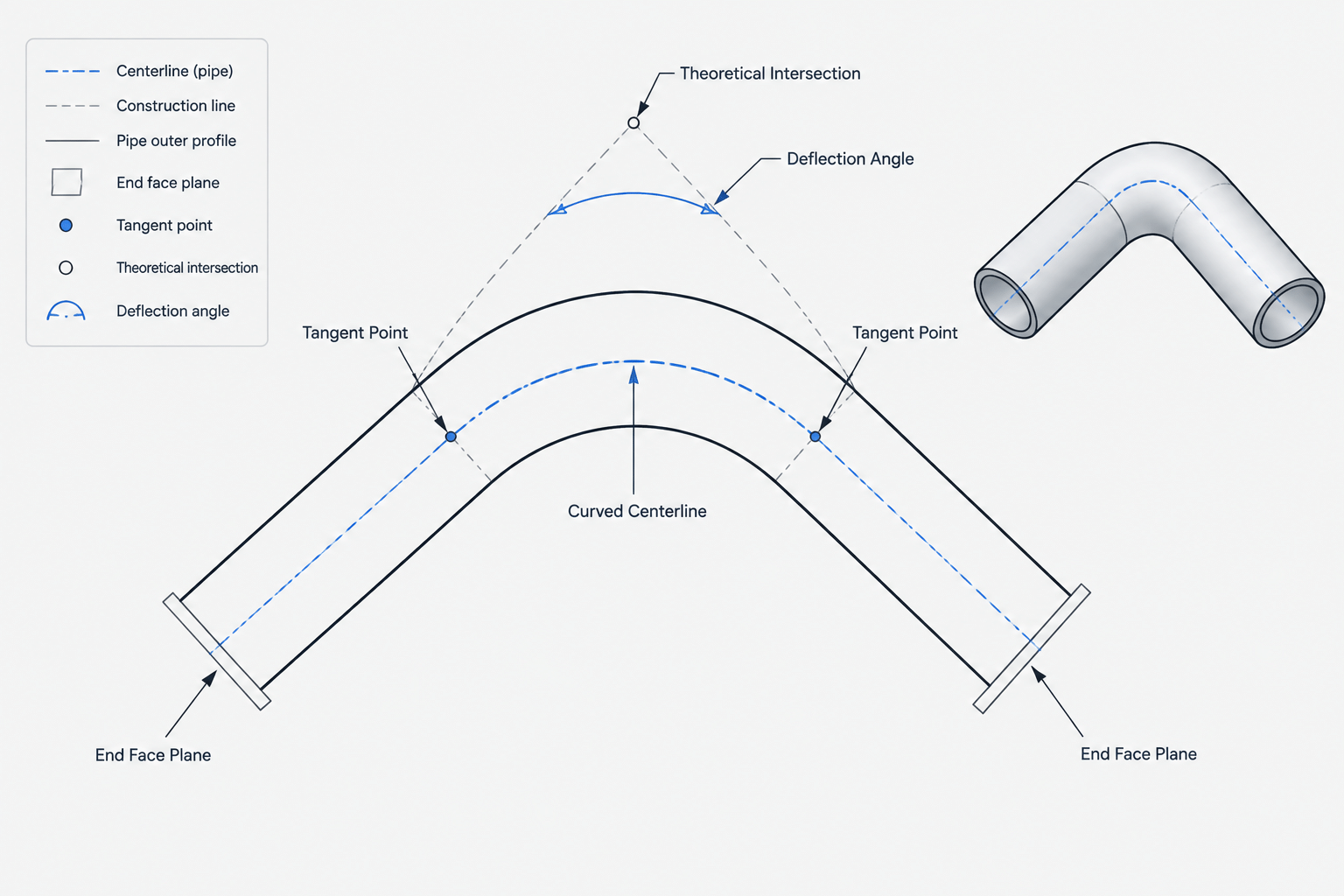
Trimmed pipe elbow CAD requires more than editing the visible shape of a fitting. The model must communicate the intended flow-path geometry, connection planes, takeout, component status, and fabrication basis without implying that a modified fitting is automatically approved or commercially available.
This guide explains how to distinguish geometric modeling from engineering acceptance. It is intended for piping designers, CAD drafters, model reviewers, and fabrication-documentation teams who need a clear definition that remains understandable in the model, isometric, bill of materials, and spool-detail workflow.
A trimmed pipe elbow is a curved fitting modified to produce a deflection angle other than its original nominal angle. It can solve a real routing problem, but it also introduces geometry and documentation issues that do not exist when an unmodified standard fitting is used.
In CAD, the common mistake is to shorten an elbow symbol or slice a solid until it appears to fit. A useful model must do more: it must preserve the intended centerline radius, place each end face correctly, provide reliable takeout dimensions, and tell fabrication and purchasing that the component is modified. Acceptance of a trimmed fitting must always be checked against the piping specification, material requirements, applicable design rules, and fabricator capabilities.
What Is a Trimmed Pipe Elbow?
A trimmed elbow begins as a manufactured elbow or elbow-shaped component from which material is removed to create a smaller angular sweep. For example, a routing condition may require an intermediate deflection rather than the nominal angle represented by the original fitting.
Trimming changes more than the visible length. It changes the location of the end face, the tangent direction at that face, the theoretical intersection of the connected pipe centerlines, and the fitting takeout used to calculate adjacent pipe lengths.
A trimmed elbow should not automatically be treated as a catalog fitting. Even if the parent elbow is a recognized standard component, the finished modified part may need a fabrication detail, special bill-of-material description, or project-specific review.
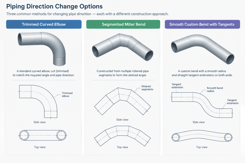
Trimmed Elbow, Miter Bend, and Custom Bend Are Different
These terms describe different fabrication concepts and should not be used interchangeably.
| Component | Basic construction | Important CAD distinction |
|---|---|---|
| Trimmed elbow | A portion of a curved elbow is removed to obtain the required angle. | Retains the curved centerline geometry of the parent fitting over the remaining sweep. |
| Miter bend | Pipe sections are cut at angles and joined to form a directional change. | Centerline direction changes at one or more discrete joints rather than along one continuous arc. |
| Custom pipe bend | Pipe is bent by an approved manufacturing process to a specified radius and angle. | May include straight tangent lengths and bend geometry that differ from a manufactured elbow. |
This distinction matters in model libraries, isometric symbols, material descriptions, weld counts, inspection planning, and replacement work. A generic “bend” label can conceal important fabrication information.
Build the Centerline Geometry First
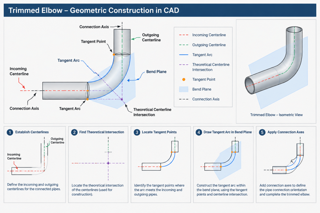
The most reliable trimmed pipe elbow CAD workflow starts with the connected pipe centerlines, not with the fitting solid.
- Establish the incoming pipe centerline.
- Establish the outgoing pipe centerline at the required deflection.
- Confirm the plane of the turn. A rolling or compound offset must not be mistaken for a simple planar elbow.
- Apply the intended elbow centerline radius.
- Construct an arc tangent to both pipe centerlines.
- Locate the arc tangent points and create end-face planes normal to the local centerline direction.
The intersection of the two straight centerlines is a theoretical point. It is useful for layout and dimensioning, but it is not a physical point on the fitting. The actual elbow occupies the curved path between the two tangent points.
Do Not Scale the Original Takeout Linearly
Reducing an elbow angle does not mean its center-to-end takeout should be reduced by the same percentage. Arc length and tangent takeout are different geometric quantities. Arc length follows the angular sweep, while the distance from a theoretical centerline intersection to a tangent point follows the tangent geometry of the bend.
For drafting purposes, construct the actual arc and measure its tangent points rather than proportionally scaling dimensions from the parent elbow. This is especially important when calculating straight pipe cut lengths between adjacent fittings.
Place the Cut Face Correctly
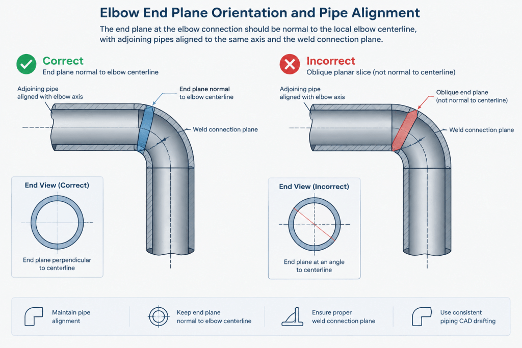
A proper elbow end face is normally established perpendicular to the local centerline at the end of the remaining arc. In a 3D model, that means the cutting plane must follow the new tangent direction.
A simple planar slice based on the original elbow end can create an oblique opening. The model may still connect visually, but the resulting face can be elliptical, misaligned with the adjoining pipe, or unsuitable as the basis for a weld-end preparation.
After trimming, check that:
- The fitting port axis matches the connected pipe axis.
- The end face is normal to that axis unless a reviewed detail intentionally states otherwise.
- The pipe and fitting centerlines are coincident.
- The nominal outside geometry meets without a visible offset.
- The end preparation is represented or referenced at the appropriate drawing level.
Detailed bevel geometry is not always needed in a plant model, but the modeled connection plane must still be correct. Fabrication drawings can then define the applicable end preparation without relying on a misleading solid.
Control the Angle with Clear References
A trimmed elbow angle should describe the change in direction between the connected pipe centerlines. Avoid ambiguous dimensions taken between arbitrary outside edges of the fitting.
Useful controlling references include:
- The incoming and outgoing pipe centerlines.
- The required deflection angle between those centerlines.
- The elbow centerline radius or identified parent fitting.
- The tangent points or theoretical centerline intersection.
- The orientation of the bend plane when the elbow is not in a principal model plane.
On an isometric, an angular note alone may not fully control a three-dimensional orientation. Coordinates, elevations, direction callouts, or a supplemental view may be needed to distinguish a planar turn from a rolled condition.
Decide Which Dimensions Govern Fabrication
Over-dimensioning a modified elbow can create a closed and conflicting dimension loop. Choose a small set of governing requirements and treat other values as reference information.
A practical detail may control the final direction, end-to-end relationship, centerline radius, and connection-plane locations. If the parent fitting must be identified, include enough information to distinguish it without implying that its original unmodified dimensions still apply.
Dimensions generated from an ideal CAD arc should not be presented as proof that the real component can be fabricated to exact model geometry. Manufacturing tolerance, fitting shape, wall behavior, cutting method, and end preparation can affect the finished part. The drawing should indicate where field verification or fabricator confirmation is required.
Describe the Modified Component in the BOM
A bill of materials should not list a trimmed elbow exactly like an unmodified elbow. Otherwise, purchasing or fabrication may supply the parent component without recognizing the required modification.
Depending on the project workflow, the description may need to identify:
- The parent elbow type and nominal size.
- The required final deflection angle.
- The applicable material and piping class reference.
- The end connection or required end preparation.
- A fabrication-detail or spool-drawing reference.
- Whether trimming is performed by the shop, fitting supplier, or another responsible party.
Do not assume that any elbow may be trimmed. The remaining end geometry, wall condition, dimensional limits, material traceability, and project rules must be reviewed by the responsible engineering and fabrication teams.
Model Library and Data Considerations
A parametric elbow object may support arbitrary angles, but that software capability does not establish that the resulting component is commercially available or acceptable for the line class. CAD systems often generate mathematically valid geometry beyond the limits of a purchasing catalog or fabrication procedure.
Keep the engineering status visible in the component data. Useful classifications include standard component, modified standard component, fabricated item, and placeholder pending vendor or shop confirmation.
If the model uses a generic variable-angle elbow, ensure that the extracted material description does not silently convert it into a standard elbow. The angle, modification status, and detail reference should survive export to isometrics and material reports.
Trimmed Elbow CAD Review Checklist
- Confirm that the required direction change cannot be handled more clearly with an available standard arrangement.
- Verify that trimming is permitted by the project piping specification and responsible engineering discipline.
- Construct the elbow from tangent centerline geometry rather than visual approximation.
- Check the centerline radius against the intended parent component or approved fabrication basis.
- Verify that both connection faces are correctly oriented to their pipe axes.
- Recalculate adjacent straight-pipe cut lengths using the actual tangent points.
- Confirm the bend plane and clocking in three dimensions.
- Identify the component as modified in the BOM and isometric notes.
- Avoid conflicting angle, takeout, coordinate, and end-to-end dimensions.
- Obtain fabrication confirmation where the model represents idealized geometry.
Use the CAD Model as a Controlled Definition
A trimmed elbow can be a compact routing solution, but it should not be treated as an ordinary elbow with a shortened graphic. Its final angle, tangent locations, cut-face planes, takeout, material description, and fabrication responsibility all need deliberate control.
The best CAD definition separates mathematical geometry from product acceptance. The model establishes where the connected pipes must run and how the modified fitting is intended to fit. The piping specification, engineering review, and fabricator determine whether that geometry can be produced and used for the actual service.
Coordinate the Model, Isometric, and Fabrication Detail
A correct solid model can still produce incomplete fabrication information if its critical properties do not transfer into downstream documents. Review the model object, isometric output, material report, and fabrication detail as a coordinated set rather than as independent deliverables.
The component identifier should remain consistent wherever the trimmed elbow appears. The isometric should show the intended directional change and modification status, while the fabrication detail should define the controlling geometry and connection planes. The bill of materials should identify the item in a way that prevents it from being mistaken for an unmodified catalog elbow.
Separate Design Requirements from Reference Information
Drawing notes should make clear which information governs fabrication and which information only helps explain the layout. Centerlines, connection locations, bend-plane orientation, and the required final direction may be controlling requirements. Values reported from ideal CAD geometry may instead be reference information when actual fitting shape or fabrication methods require confirmation.
This distinction reduces the risk of conflicting dimension loops. It also helps the fabricator identify questions before cutting the parent component or preparing adjoining pipe.
Plan for Revision and Replacement
A modified component should remain identifiable after the original design team has completed its work. Preserve the modification description, parent-component basis, material or piping-class reference, and associated detail reference in the project record. A generic elbow graphic without this data can cause confusion during later maintenance, replacement, or model conversion.
If routing geometry changes, recheck the tangent points, adjacent pipe cut lengths, connection-face orientation, and extracted material description. Moving an endpoint without rebuilding the underlying bend geometry can leave apparently connected objects with incorrect takeout or port data.
Final Handoff Review
- Geometry: Confirm that the connected pipe axes, elbow arc, tangent points, and connection planes agree.
- Classification: Identify the item as modified or fabricated rather than allowing it to appear as an ordinary standard elbow.
- Documentation: Ensure that the angle, bend-plane orientation, and governing fabrication references are visible in the appropriate deliverables.
- Extraction: Check that isometric and material-report output preserve the modification status and do not substitute a generic description.
- Approval: Record the required engineering, specification, supplier, or fabricator review without treating CAD geometry as acceptance evidence.
Frequently Asked Questions
Is a trimmed elbow the same as a variable-angle elbow in a CAD library?
Not necessarily. A variable-angle object is a software function that can create geometry at a selected deflection. A trimmed elbow is a physical modification concept. The software object must still be matched to an acceptable parent component, fabrication method, material requirement, and project specification.
Can a trimmed elbow takeout be found by scaling the parent elbow takeout?
Proportional scaling is not a reliable method because tangent takeout and arc length describe different geometric relationships. Construct the required centerline arc, locate its tangent points, and derive adjoining pipe lengths from that geometry.
What determines the orientation of the trimmed end face?
The connection face is generally established normal to the local centerline direction at the end of the remaining arc, unless an approved fabrication detail defines another condition. The modeled port axis and adjoining pipe axis should align.
Does a valid CAD model prove that the fitting can be fabricated?
No. CAD can define mathematically consistent geometry, but it does not confirm specification acceptance, available fitting shape, remaining wall condition, traceability, cutting limits, end preparation, or fabricator capability.
How should a trimmed elbow appear in the bill of materials?
The description should clearly distinguish it from an unmodified elbow and retain the information needed by the project workflow, such as the parent-component basis, final deflection, material or class reference, end connection, and fabrication-detail reference.
When is a supplemental drawing view helpful?
A supplemental view is useful when the bend plane, roll, clocking, or connection-face orientation cannot be understood clearly from the isometric alone. It should clarify the geometry without adding conflicting controlling dimensions.