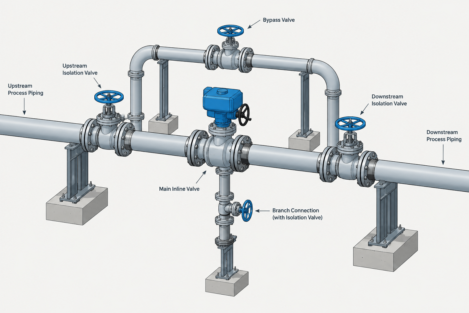
Valve bypass piping in CAD must translate process intent into a layout that can be operated, isolated, fabricated, and maintained. The visible loop is only one part of the design problem. Branch locations, valve orientation, removable joints, support intent, trapped pockets, and access envelopes all affect whether the modeled station performs as intended.
This guide explains how to review a bypass as a complete piping assembly. Use it alongside the approved P&ID, line list, piping material specification, valve information, operating philosophy, and project CAD requirements. Where those documents disagree or leave the bypass function unclear, obtain discipline confirmation rather than resolving the issue through a modeling assumption.
A valve bypass is a secondary flow path routed around a valve, equipment item, or other section of the main process line. Although the geometry may look simple, the bypass often carries important operating and maintenance intent. A CAD model that shows only a convenient loop can miss valve sequence, accessibility, drainage, specification boundaries, or the space needed to remove the main-line component.
Valve bypass piping in CAD should therefore be treated as a functional assembly rather than an arbitrary branch connection. The designer must reconcile the P&ID, line list, piping material specification, equipment or valve data, and project operating philosophy before finalizing the layout.
Why a Bypass Is Provided
Bypasses are used for different reasons, and the reason affects the arrangement. Common purposes include:
- Maintaining limited flow while a main valve or component is isolated for maintenance.
- Equalizing pressure across a closed valve before the main valve is operated.
- Providing a manual flow path around a control valve station under an approved operating procedure.
- Supporting startup, shutdown, warming, flushing, or commissioning activities.
- Allowing temporary operation while a replaceable inline item is removed.
These functions are not interchangeable. A small equalizing line should not automatically be interpreted as an operating bypass, and a control valve bypass should not be assumed capable of carrying normal process flow. CAD geometry alone cannot establish capacity or operating permission. Those decisions require verified process and piping information.
Typical Elements of a Valve Bypass Assembly
A bypass arrangement usually includes more than the bypass pipe itself. Depending on the design, it may contain branch connections, isolation valves, a bypass valve, vents, drains, instruments, reducers, unions, flanges, or removable spool pieces.
| Element | Typical function | CAD concern |
|---|---|---|
| Main-line isolation valves | Isolate the primary valve or inline component | Operator access, removal space, orientation, and face-to-face dimensions |
| Bypass valve | Controls or isolates flow through the alternate path | Flow direction, operator clearance, end connections, and maintainability |
| Branch connections | Connect the bypass to the main line | Connection type, reinforcement requirements, branch orientation, and weld access |
| Reducers | Transition between main-line and bypass sizes | Size order, eccentric or concentric orientation, and specification compatibility |
| Vent or drain | Relieves trapped pressure or removes retained liquid | High-point or low-point location, discharge destination, and accessibility |
| Breakable connections | Permit removal of the main component or bypass section | Bolt withdrawal, flange separation, spool extraction, and field assembly space |
Not every station requires every element. The P&ID and approved project documents should define the intended components. The CAD designer should not add a bypass merely because a similar station has one.
Read the P&ID as an Operating Arrangement
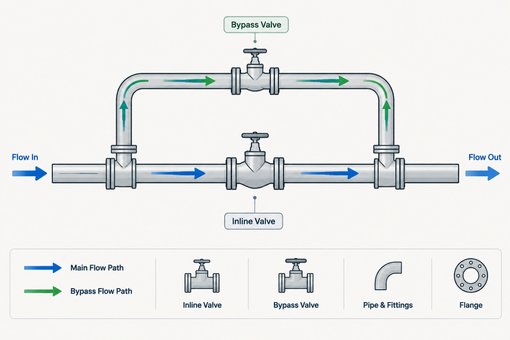
Begin by tracing every possible flow path on the P&ID. Identify the main valve or component, the upstream and downstream isolation points, and the points where the bypass reconnects. Confirm whether flow through the bypass is controlled manually, automatically, or only under a special procedure.
Also review valve states and annotations. A normally closed bypass valve carries different operational meaning from a valve shown without a defined normal position. However, normal position does not by itself prove that a route is safe for continuous service. Any ambiguity should be returned to the responsible process or piping discipline rather than resolved through drafting assumptions.
Check whether the bypass retains the same line number as the main run or receives a separate designation. Project numbering practices vary. Size changes, material changes, insulation changes, or service changes may also create specification or documentation boundaries that must appear consistently in the model, isometric, and bill of materials.
Choose the Branch Locations Deliberately
The two bypass connections must isolate the intended main-line item without unintentionally bypassing another required component. For example, locating a takeoff on the wrong side of an isolation valve may prevent maintenance isolation or create a trapped section that was not apparent on the schematic.
Branch locations also affect fabrication and inspection. Avoid crowding a bypass connection against a main-line weld, flange, reducer, support attachment, or another branch. Exact separation requirements must come from the governing design basis and fabrication rules; a visually clear CAD model is not proof of acceptable spacing.
Where practical, arrange the branches so that the bypass can be fabricated, welded, inspected, insulated, and maintained. A compact loop may save model space but create inaccessible welds or prevent tools from reaching valve packing, bolting, or operators.
Lay Out the Bypass for Real Access
A bypass is often routed above, below, or beside the main valve station. Each option has consequences:
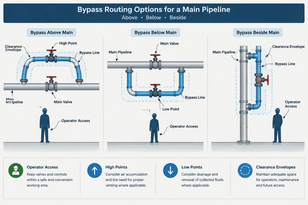
- Above the main line: May preserve floor access but can place operators beyond reach and create high points that require review.
- Below the main line: May improve operator access but can obstruct walkways, collect liquid, or conflict with drains and supports.
- Beside the main line: Can simplify operation but may increase the station width and interfere with adjacent piping.
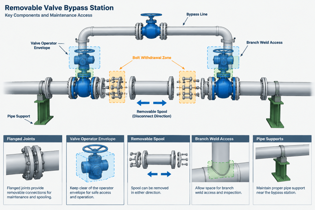
Model valve handwheels, levers, gear operators, actuators, and stem travel envelopes where they influence access or clashes. A valve body that fits between pipes does not guarantee that the valve can be operated or removed. Confirm that personnel can approach the station and that nearby steel, cable tray, insulation, and other valves do not block movement.
Preserve removal paths
If the main valve or inline component is intended to be removable, identify how it leaves the assembly. Check the space required to separate flanges, withdraw bolts where applicable, handle the component, and move it away from the line. The bypass should not cross the planned extraction path.
Similarly, a removable bypass spool needs a credible disassembly sequence. Showing flanges or unions does not automatically make a rigid loop removable if the surrounding piping cannot move enough to release it.
Account for Drainage, Venting, and Trapped Pressure
A bypass loop can create high points, low points, and isolated pockets. These conditions may matter even when the bypass is normally closed. Liquid can remain trapped between closed valves, gas can collect at an elevated section, and thermal expansion of blocked-in liquid can become a design concern.
The CAD designer should identify these geometrical conditions and request discipline review where the documents do not clearly address them. Do not add vents, drains, or pressure-relief devices solely as a drafting convenience. Their need, size, connection, and discharge routing require engineering confirmation.
When a drain or vent is specified, model its destination rather than ending it ambiguously in space. The outlet may connect to another system, terminate at an approved location, or require a separate detail. The drawing should distinguish a process connection from an open drain, temporary hose point, or plugged branch.
Coordinate Supports and Flexibility
Small bypass piping can still impose loads on main-line branches and valve bodies. A rigid loop tied closely to the main run may experience fit-up difficulty or thermal movement. Conversely, a long unsupported bypass may be vulnerable to vibration, sagging, or accidental loading.
Show support intent without assuming that a nearby main-line support automatically restrains the bypass. Coordinate support locations with valve access, welds, insulation, and removable joints. Where thermal movement, vibration, weight, or branch loading is significant, obtain the appropriate piping stress or mechanical review rather than judging adequacy from appearance.
Isometric and Model Data Checks
The bypass must remain recognizable and complete when extracted to an isometric or fabrication drawing. Before issue, verify:
- Both bypass connection points match the approved schematic.
- Pipe size, schedule or wall designation, material class, and end connections are populated from controlled data.
- Valve tags, types, normal positions, and flow directions agree with project documents.
- Reducers are oriented and listed correctly.
- Branch fittings and reinforcement information are not lost during drawing extraction.
- Dimensions locate the branches and valves without creating contradictory closed dimension chains.
- Shop welds, field welds, and removable joints support a realistic assembly sequence.
- Insulation and tracing requirements are applied consistently where specified.
- The bill of materials includes the bypass components without duplicating main-line items.
A useful review technique is to highlight the main flow path and bypass flow path in separate temporary model colors. Trace each route from upstream to downstream, then compare every component and connection against the P&ID. Remove the review colors before formal issue unless the project uses them as part of an approved status convention.
Avoid Copying a “Typical” Station Without Verification
Reusing a proven CAD assembly can improve consistency, but a bypass station is not universal. Different services may require different materials, valve types, branch methods, operator arrangements, drainage provisions, or maintenance strategies. Even geometrically identical stations may have different line data and operating intent.
Use library assemblies as layout starting points only. Replace component data from the current project specification, confirm all connection dimensions, and review the resulting station in its actual surroundings. The final model should communicate an approved process path, a constructible piping assembly, and a maintainable operating arrangement—not merely a neat loop around a valve.
Practical CAD Review Sequence
A structured review helps separate process questions from layout and data-quality issues. Begin with system intent, then examine the physical arrangement and finally confirm drawing extraction and model attributes.
- Trace the process paths: Follow the main route and the alternate route between their connection points. Confirm which component the bypass is intended to go around.
- Identify the isolation boundary: Check whether the modeled valve arrangement can isolate the intended item without defeating another required function.
- Review operating access: Examine handwheels, levers, actuators, stem movement, approach space, and visibility of tags or indicators.
- Test maintenance logic: Visualize flange separation, bolt handling, spool release, lifting access, and the path used to remove the main component.
- Inspect the piping profile: Look for high points, low points, retained liquid, trapped gas, and blocked-in sections that require engineering review.
- Check constructibility: Confirm that branch connections, welds, fittings, supports, insulation, and field joints can be accessed in the intended fabrication sequence.
- Validate model data: Compare component properties, tags, line assignments, connection types, and specification boundaries with controlled project information.
- Review extracted deliverables: Make sure the bypass remains understandable in isometrics, plans, sections, material reports, and maintenance views.
Questions to Resolve Before Model Approval
The model reviewer should be able to explain why the bypass exists, when it may be used, what must be isolated, and how the station will be maintained. The reviewer should also know which decisions are established by project documents and which remain open engineering actions.
Unresolved process capacity, pressure control, relief, valve selection, branch reinforcement, flexibility, or support-load questions should be assigned to the responsible discipline. CAD coordination can reveal these issues, but model geometry alone cannot settle them.
What a Clear Deliverable Should Communicate
A well-coordinated bypass layout allows another technical user to distinguish the main flow route from the alternate route and understand the intended isolation boundary. Valve tags, flow direction, line data, breakable connections, supports, vents, drains, and specification changes should remain consistent across the model and derived documents.
Clarity does not mean adding unapproved components or annotations. It means accurately representing the approved design, exposing conflicts early, and documenting questions that require engineering resolution.
Valve Bypass Piping in CAD FAQs
Is every small line around a valve an operating bypass?
No. The line may serve equalization, warming, flushing, startup, drainage, or another limited function. Its permitted use must be confirmed from approved process and operating information rather than inferred from its shape.
Can a bypass be added because a similar valve station has one?
No. A previous assembly may be useful as a layout reference, but the need for a bypass and its components must come from the current project documents and responsible engineering disciplines.
Should the bypass be routed above or below the main line?
There is no universal routing choice. The arrangement depends on access, drainage, venting, surrounding equipment, supports, maintenance paths, operator location, and project requirements. Each option should be evaluated in its actual model context.
Why are valve operator envelopes important?
The valve body may fit while its handwheel, lever, actuator, stem movement, or maintenance access conflicts with nearby piping or structure. Modeling the relevant envelope helps identify these problems before fabrication.
Does adding flanges make a bypass spool removable?
Not necessarily. The assembly also needs sufficient freedom for joint separation, fastener handling, spool movement, and extraction. The proposed disassembly sequence should be reviewed in the surrounding layout.
Who determines whether a bypass needs a vent, drain, or relief provision?
That decision requires engineering review based on the service, operating conditions, isolation arrangement, and project design basis. A CAD designer should flag trapped pockets but should not add such components without authorization.
What should be checked when the model is converted to an isometric?
Confirm that connection points, component tags, flow direction, reducers, branches, removable joints, weld status, dimensions, line data, and material reporting remain complete and consistent with the approved design.