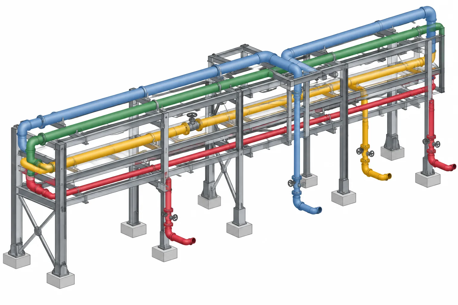
A pipe rack may look orderly in a finished model, but that arrangement is usually the result of many competing decisions. Process sequence, pipe size, insulation, thermal movement, support needs, equipment connections, access, structural framing, and future expansion can all influence where a line belongs.
Effective pipe rack routing in CAD is therefore more than placing parallel centerlines. The model should establish a routing system that remains understandable as lines are added, reviewed, and revised. Levels, lanes, crossovers, and branch exits must work together without creating unnecessary elevation changes or blocking maintenance access.
What a pipe rack routing plan controls
A routing plan provides a shared framework for locating multiple lines within the same supporting structure. It typically controls or records:
- The direction and limits of the rack.
- Rack levels and their reference elevations.
- Preferred lanes or routing zones.
- Locations where lines enter, leave, rise, drop, or cross.
- Interfaces with structural beams, columns, bracing, and support steel.
- Space reserved for electrical, instrumentation, utilities, or future piping.
- Areas affected by thermal movement, expansion features, or special supports.
The routing plan does not replace the line list, piping specification, stress review, or structural design. It connects those inputs to physical geometry so that the overall arrangement can be coordinated.
Start with a rack coordinate framework
Before assigning individual lines, establish a stable coordinate framework. Identify the rack centerline or structural grid, plant orientation, column lines, support elevations, and the physical limits of each rack segment. Use project datums rather than temporary model geometry whenever possible.
Divide a long rack into recognizable zones. Column bays often provide useful location references, but the project may use another established grid. A designer should be able to describe a routing issue by rack, level, side, and bay without relying only on a screen capture.
Confirm how elevations are reported. A rack drawing may reference steel elevation, pipe centerline elevation, bottom of pipe, or another project datum. Mixing these conventions can create a systematic vertical error even when every modeled line appears internally consistent.
Organize the rack with levels and lanes
Rack levels
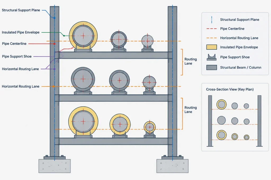
A level is a vertical routing zone, not simply a single shared centerline elevation. Pipes with different outside diameters may rest on the same support steel while having different centerline elevations. Insulated lines, shoes, saddles, and special support details can create additional differences.
Modelers should distinguish the structural support plane from the pipe centerline. If every line is forced onto one centerline elevation, the model may incorrectly show smaller and larger pipes floating above or passing through the support surface.
Rack lanes
A lane is a horizontal allocation across the rack width. It may contain one line, a group of related lines, or a reserved corridor. Lane planning helps prevent the rack from becoming a first-come, first-served collection of centerlines.
Common lane-assignment considerations include:
- Where each line originates and terminates.
- Whether branches leave from one side of the rack.
- Pipe outside diameter, insulation envelope, and flange projections.
- Expected thermal movement and guide or anchor locations.
- Valve, strainer, instrument, and maintenance access.
- Whether the line is likely to require future connections.
- Compatibility with neighboring services under project rules.
Lane names or identifiers can be useful during design, even if they do not appear on final drawings. They allow the team to discuss allocations consistently and make changes without losing the original planning logic.
Group lines by routing behavior, not only by service
Lines from the same process system do not always belong next to one another. A better arrangement considers how each line behaves geometrically and mechanically.
| Routing characteristic | CAD planning implication |
|---|---|
| Frequent branch exits | Place the line where branches can leave without crossing many neighboring pipes. |
| Large thermal movement | Reserve movement space and coordinate anchors, guides, loops, or offsets before adjacent lanes become fixed. |
| Regular valve access | Avoid burying operators between inaccessible rows or directly under obstructing steel. |
| Large fittings or flanges | Check actual component envelopes rather than relying only on pipe centerline spacing. |
| Sloped service | Coordinate changing centerline elevations with support steel and crossing lines. |
| Future extension | Preserve a credible route to the rack edge or continuation point. |
This approach reduces avoidable crossovers and makes branch routing more predictable. It also helps reviewers understand why a line occupies a particular lane.
Plan entries, exits, and branch drops early
The most congested areas of a rack are often not the long straight runs. Congestion develops where lines enter from equipment, leave toward process units, change elevation, or branch down through multiple levels.
Identify these transition zones before filling the rack interior. For each line, determine:
- Which side of the rack provides the most direct approach.
- Whether the line must pass over or under another level.
- Where elbows, reducers, valves, and flanges enlarge the routing envelope.
- Whether a vertical drop conflicts with beams, bracing, cable trays, or lower-level piping.
- How the branch will be supported after leaving the main rack.
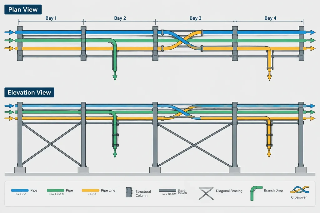
A branch that looks clear in plan may be blocked in elevation by structural bracing or another rack level. Review plan, elevation, section, and 3D views together rather than treating the plan as the only routing authority.
Use crossovers deliberately
A crossover allows one line to change its order relative to neighboring lines, but it introduces elbows, elevation changes, supports, and possible drainage or venting consequences. It can also consume space needed by other systems.
Before adding a crossover, ask whether the problem can be solved by changing the original lane assignment. When a crossover is necessary, place it in a zone with enough vertical and horizontal clearance for the complete fitting geometry. Check insulation, flange envelopes, weld access, support locations, and the path of nearby branches.
Do not model a crossover as an isolated geometric jog. Its effect continues along the rack because the line may occupy a different lane or level afterward. Update routing diagrams, line assignments, and downstream coordination views accordingly.
Account for thermal movement and support behavior
Pipe rack layout and flexibility planning are closely related. A straight route may appear efficient but can be unsuitable if it leaves no space for expected movement or for the support arrangement identified during flexibility review.
The CAD model should clearly represent known anchors, guides, line stops, sliding supports, springs, or other support concepts at the level appropriate to the project phase. Where support design is incomplete, reserve space and mark the interface rather than assuming ordinary supports will be adequate.
Expansion loops and offsets should not be inserted solely because space appears available. Their geometry, location, and support behavior require engineering review. The piping designer’s role is to preserve a workable corridor, coordinate surrounding objects, and incorporate the reviewed arrangement into the model.
Model the real routing envelope
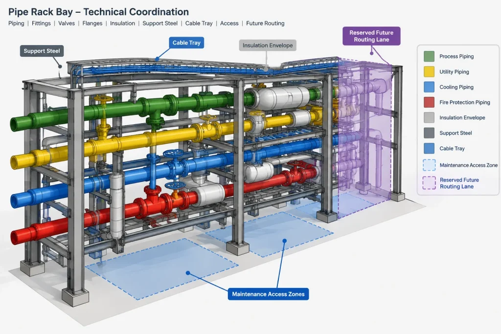
Centerlines are useful for early studies, but final coordination requires more than nominal pipe size. The effective envelope may include pipe outside diameter, insulation, jacketing, flanges, valve bodies, operators, drains, vents, instrument connections, shoes, and movement clearance.
Use simplified geometry when appropriate, but do not simplify away the feature that controls clearance. For example, a valve body may fit between adjacent lines while its handwheel, actuator, or removal path does not. Similarly, two insulated pipes may clear each other while their shoes compete for the same support steel.
Coordinate ownership at rack interfaces
Rack routing crosses several design disciplines. Define who controls the structural grid, support elevations, reserved zones, penetrations, and loading information. Piping may propose a route, but structural members should not be moved or modified without the responsible discipline’s review.
At minimum, coordination should address:
- Beam, column, and bracing geometry.
- Pipe support attachment locations and load handoffs.
- Cable tray, duct, and instrument routing zones.
- Platforms, ladders, stairs, and escape paths.
- Equipment access and lifting or removal routes.
- Rack extensions and future-use reservations.
Reserved space should be modeled or documented visibly. Empty model space is easily mistaken for available space when its purpose is not identified.
A practical CAD review sequence
- Verify references: Confirm rack grids, orientation, levels, and project datums.
- Review line inputs: Check line numbers, sizes, specifications, insulation status, endpoints, and known slope or flexibility needs.
- Assign lanes: Group lines according to exits, branches, component envelopes, and movement behavior.
- Route transitions: Develop entries, exits, drops, rises, and crossovers before finalizing long straight runs.
- Add controlling components: Place large valves, flanges, strainers, instruments, and support features that affect clearance.
- Check all views: Review plan, elevation, section, and 3D geometry at congested bays.
- Coordinate disciplines: Resolve conflicts with steel, trays, access systems, and equipment maintenance zones.
- Reconcile deliverables: Confirm that isometrics, support information, line lists, and the coordinated model describe the same routing.
Common pipe rack modeling mistakes
- Assigning lanes without considering where branches must leave.
- Using one centerline elevation for pipes resting on a common support plane.
- Checking bare pipe clearance while ignoring insulation and components.
- Adding crossovers late, after surrounding lanes are already fixed.
- Routing vertical drops through beams or bracing that are hidden in plan view.
- Treating reserved future space as unused space.
- Placing valves where operators are visible but not safely accessible.
- Assuming that a clash-free model is automatically supportable or flexible.
Keep the routing logic visible
A well-organized pipe rack model should communicate why lines are arranged as they are. Use consistent object data, level names, model views, notes, or planning diagrams to preserve lane assignments and reserved zones. When a revision moves a line, review its full route rather than only the edited bay.
The best rack layout is not necessarily the one with the fewest bends or the tightest spacing. It is the arrangement that carries each line to its destination while remaining supportable, maintainable, coordinated, and understandable in the project deliverables.