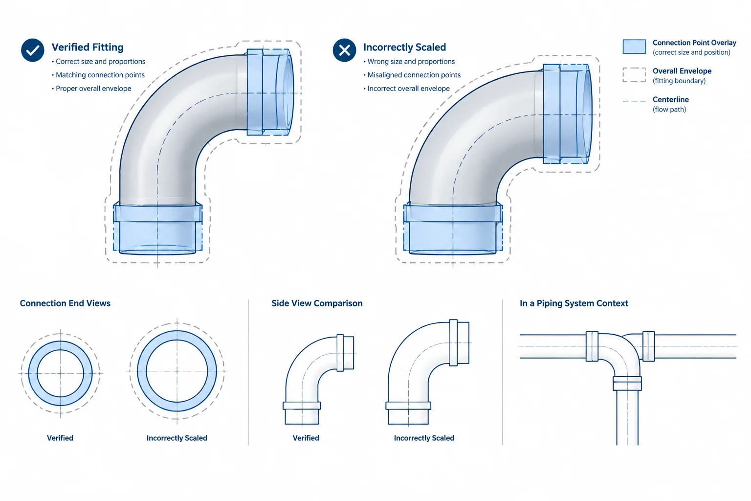
A CAD scale command changes geometry mathematically; it does not select a valid piping component from a dimensional system. This distinction matters whenever a block influences connection locations, routing, clearances, cut lengths, material reporting, or fabrication information.
The guidance below explains why visual similarity is insufficient and how to distinguish acceptable drawing-scale changes from unverified changes to physical component geometry.
Scaling a piping CAD block may seem like a quick way to create a missing pipe, fitting, flange, or valve size. The result often looks reasonable on screen, especially when the source and target sizes are close. However, a uniformly enlarged or reduced component is usually not a valid representation of the new nominal size.
Piping components are not families of geometrically similar objects. Their outside diameters, wall thicknesses, fitting takeouts, flange details, bores, and connection geometry do not necessarily change by the same ratio. A scaled block can therefore introduce errors that remain hidden until dimensioning, spool development, interference review, or fabrication.
The safer principle is simple: use scaling to control drawing representation, not to invent technical dimensions.
Why piping components do not scale proportionally
Uniform scaling assumes that every dimension on an object changes by one common factor. That assumption works for a map symbol or a conceptual diagram, but it does not describe how standardized piping component sizes are organized.
A pipe size is nominal. Its designation is not a scale factor, and it should not be treated as a direct geometric measurement. Pipe outside diameter follows the applicable dimensional system, while inside diameter depends on the selected wall thickness. As a result, changing nominal size is not equivalent to multiplying the entire cross-section by a ratio.
Fittings add more independent dimensions. An elbow includes connection diameters and center-to-end geometry. A tee includes run and branch connections plus center-to-end dimensions. A reducer combines two end sizes, an overall length, and a profile between them. Flanges and valves may include additional dimensions such as facing geometry, bolt-circle layout, hub shape, body envelope, and end-to-end length.
These dimensions belong to a defined component configuration. They must be selected or verified individually rather than inferred from the appearance of another size.
What goes wrong when a block is scaled
Connection diameters become unreliable
A scaled fitting end may no longer match the verified outside diameter or connection geometry of the adjoining pipe. In a single-line diagram this discrepancy may not be visible. In a double-line drawing or 3D model, it can create a step, gap, overlap, or false alignment at the joint.
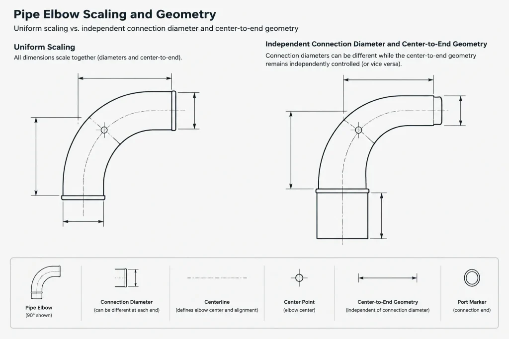
The problem can be more serious when the component has dissimilar ends. A reducing component contains at least two size-dependent connections, so one scale factor cannot independently establish both required ends.
Takeouts and end-to-end dimensions are distorted
Elbow takeouts, tee center-to-end dimensions, valve face-to-face lengths, and fitting overall lengths affect the position of connected pipe. If one of these dimensions is generated by scaling rather than verified data, every downstream coordinate may shift.
A model can remain visually connected while still producing incorrect cut lengths. This is especially risky when dimensions are taken directly from block extents or connection points.
Flange details no longer represent a coordinated joint
A flange is not only a circular outline. Its joint geometry may include a bore, outside envelope, facing, thickness, hub, bolt circle, bolt-hole count, and hole size. These features do not necessarily progress proportionally between nominal sizes or pressure classes.
Scaling a flange can create a drawing in which bolt holes appear evenly arranged but do not represent the intended component. Scaling should never be used to derive drilling or joint dimensions.
Wall thickness is misrepresented
If a hollow pipe or fitting is scaled uniformly, both its outside and inside geometry change by the same ratio. Actual wall selection does not work that way. Pipe schedule or another wall designation determines the applicable wall thickness for a given nominal size, subject to the governing product data.
A scaled annular shape can therefore show an invented bore and wall thickness. Even when the outer silhouette looks acceptable, the internal geometry may be wrong.
Metadata can disagree with geometry
Changing a block name, tag, attribute, or catalog description does not update incorrect geometry. A component labeled with the target size may still retain the dimensions of the source component multiplied by an arbitrary factor.
This creates a particularly dangerous condition: the drawing looks organized, and the bill of materials may list the intended item, but the model geometry does not correspond to that item.

Scaling the view is different from scaling the component
Not every use of scale is improper. The important distinction is between presentation scale and physical component scale.
| Action | Typical purpose | Engineering implication |
|---|---|---|
| Changing viewport or plotted drawing scale | Fit a model onto a sheet | Model dimensions remain unchanged |
| Adjusting annotation or symbol size | Keep text and schematic symbols readable | May be acceptable when the object is intentionally non-dimensional |
| Scaling a reference image | Align a scan or background for tracing | Requires calibration against known control dimensions |
| Scaling a physical piping component | Attempt to create another nominal size | Usually produces unverified geometry |
P&ID symbols are commonly schematic and are not intended to show physical component envelopes. Their visual size may be adjusted to maintain clarity, provided the drafting convention remains consistent. A piping plan, fabrication isometric, spool drawing, or coordinated 3D model has a different purpose: its component geometry may control dimensions, clearances, quantities, and interfaces.
A safer workflow for creating a missing component size
1. Identify the component configuration
Start with more than the nominal size. Determine the component type, end connections, wall or bore basis where relevant, pressure class or rating designation where applicable, material specification context, facing or end preparation, and any reducing size combination.
Two components with the same nominal size may have different controlling dimensions because they belong to different configurations.
2. Establish the authoritative dimensions
Use the project-approved component catalog, manufacturer information, or the dimensional standard specified by the project. Do not estimate missing values from a neighboring size. Also confirm that the source applies to the exact type being modeled.
PipeSTD reference pages can assist with terminology and dimensional lookup, but project requirements still control the component selected for actual design work.
3. Build around connection points
Define the ports or insertion points before refining the outer profile. For many piping models, the most important geometric controls are:
- End locations and connection axes
- Nominal connection sizes
- End type and mating condition
- Center-to-end or end-to-end dimensions
- Flow or branch direction where applicable
- Orientation reference and component centerline
A visually detailed body cannot compensate for misplaced ports. Correct connection geometry should drive the component.
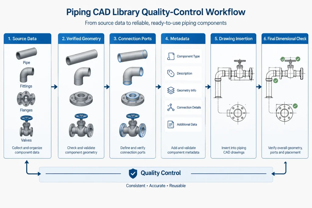
4. Model only the detail required
A coordination model may need a reliable outer envelope, connection locations, and maintenance space without every manufacturing feature. A fabrication detail may require much more precise end and bore information. Match the model detail to its intended use, but do not replace known dimensions with scaled approximations.
5. Populate and check metadata
Assign size, description, specification, end connection, and other project fields only after confirming the geometry. Where the CAD workflow supports automated schedules or bills of material, test that the new component reports the intended data.
6. Compare against independent controls
Before releasing the component, check several dimensions that are not all derived from the same construction step. For example, verify port spacing, connection diameter, overall envelope, and orientation. For a flanged item, review the flange interfaces separately from the body envelope.
How to handle legacy drawings that contain scaled blocks
Scaled piping blocks are common in older drawings and mixed-source CAD libraries. Their presence does not automatically mean the entire drawing is unusable, but they should be treated as unverified until checked.
- Inspect scale factors: Identify block instances with non-default or nonuniform scaling.
- Separate symbols from physical components: A scaled schematic symbol may be intentional; a scaled fabrication component requires review.
- Measure controlling geometry: Check connection spacing, diameters, takeouts, and overall dimensions against approved data.
- Review attributes: Confirm that size and description fields agree with the geometry.
- Replace rather than rescale: Substitute a verified component definition when one is available.
- Recheck connected routing: Replacing an incorrect block may move adjacent pipe ends, dimensions, supports, or equipment interfaces.
Nonuniform scaling deserves special attention because it can distort circular features into ellipses and alter angles. It is generally unsuitable for physical piping components, even when it appears to solve a space problem in a view.
Library practices that prevent scaling errors
A well-managed CAD library should make the correct action easier than the shortcut. Use clear component names, separate schematic symbols from dimensional blocks, record the dimensional basis, and provide defined insertion points. If a size is unavailable, mark it as missing instead of encouraging users to derive it through scaling.
Parametric or catalog-driven components can reduce repetitive drafting, but parameterization does not remove the need for verified data. Each supported size and configuration must still produce the correct dimensions and connection behavior.
Scaling a piping CAD block can produce a convincing picture, but visual similarity is not dimensional validity. When geometry affects fit-up, routing, clearance, cut length, bolting, or material reporting, create or obtain the actual component configuration and verify it before use.
A practical release check for piping blocks
Before treating a newly created or inherited block as dimensional, determine where its geometry came from. A descriptive name, correct-looking outline, or completed attribute set does not establish that the component matches approved dimensional data.
- Check the block transform: Look for uniform or nonuniform instance scaling that may conceal altered geometry.
- Trace the dimensional basis: Confirm that connection locations, envelopes, bores, and other controlling features came from an approved source rather than a scale ratio.
- Inspect dependent objects: Review connected pipe, dimensions, supports, equipment interfaces, and annotations that may have been positioned from the block.
- Separate geometry from identification: Verify that catalog fields and block attributes describe the geometry actually shown.
- Control the replacement: If the block is unverified, replace it with the correct definition and then review affected routing and reported quantities.
Why exploding a scaled block does not correct it
Exploding converts a block instance into editable drawing objects, but it does not restore the dimensions that existed before scaling or supply the dimensions of another nominal size. The resulting lines and arcs remain based on the transformed geometry. They must still be checked and reconstructed from verified component data.
When a placeholder may be acceptable
A temporary placeholder can support early layout work if it is clearly identified as non-dimensional, excluded from material reporting, and prevented from controlling fabrication or interface decisions. The project team should also have a defined process for replacing it. A placeholder becomes risky when its apparent precision encourages users to dimension from it or treat it as an approved catalog component.
Frequently asked questions
Can a piping block be scaled if only its plotted appearance needs to change?
Change the viewport, plotting setup, annotation behavior, or other presentation controls instead of changing physical component geometry. Schematic symbols may follow separate drafting conventions because they do not necessarily represent a dimensional envelope.
Does uniform scaling preserve the accuracy of a fitting?
No. Uniform scaling preserves geometric similarity, but piping sizes are not generally defined as proportional copies. Connections, takeouts, wall geometry, and body details may follow different dimensional relationships.
Is nonuniform scaling acceptable for a physical piping component?
It should not be used to establish dimensional component geometry. It can distort circular features, angles, connection faces, and body proportions independently, making visual and dimensional checks more difficult.
Can a dynamic or parametric block generate multiple pipe sizes?
Yes, but only when its parameters use verified dimensions and valid configuration rules for every supported component. A parameter that merely enlarges the source geometry remains a scaling shortcut.
How can I tell whether a legacy block was scaled?
Inspect the block instance properties and compare controlling geometry with approved component data. Also review nested blocks, because scaling may exist inside a parent definition rather than at the visible instance.
Does renaming the block make it valid for the target size?
No. Names, descriptions, and attributes identify an object but do not correct its geometry. Identification data and physical dimensions must be verified separately and then checked for agreement.