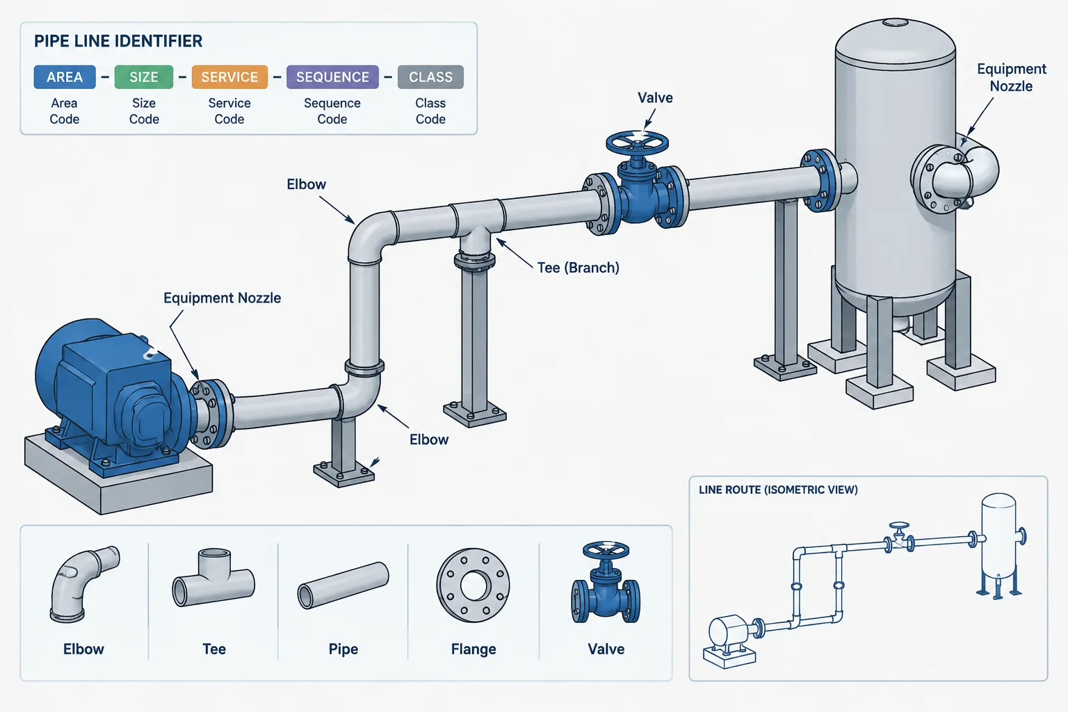
Learning how to read a piping line number is less about memorizing a code pattern and more about knowing where each field is defined. Familiar-looking abbreviations can have different meanings between projects, so the identifier must be interpreted through the applicable legend, line list, piping specifications, and CAD data.
This guide explains how service, nominal size, sequence, piping class, and optional modifiers relate to pipeline identity. It also shows how to distinguish a line number from component tags, spool numbers, piece marks, and weld numbers during design and drawing review.
Before decoding the identifier
- Confirm the project convention: Check field order, separators, abbreviations, and optional suffixes.
- Identify the controlling data source: Determine whether the approved line list, project database, or another controlled document governs each attribute.
- Read the complete route: Follow the line through branches, reducers, specification breaks, equipment connections, and drawing continuations.
- Avoid assumptions: Do not infer wall thickness, component materials, or connection details from an unexplained code.
A piping line number is a compact identifier used to connect process intent, engineering data, CAD geometry, drawings, and material requirements. It may appear beside a line on a P&ID, in a line list, on an isometric, or as an attribute attached to a routed pipeline in a model.
Although line numbers often contain recognizable fields, there is no single universal format. Each company or project establishes its own numbering convention. A designer should therefore treat the project line-number legend and line list as controlling references rather than attempting to decode an identifier from experience alone.
What a piping line number identifies
A line number generally identifies an engineering pipeline or line segment, not an individual length of pipe. The same line number can apply to straight pipe, elbows, tees, reducers, flanges, valves, and other inline components that belong to the same defined pipeline.
This distinction matters in CAD. A pipe spool, fabrication piece, weld, component tag, and line number serve different purposes:
- Line number: identifies a pipeline or defined portion of a pipeline.
- Component tag: identifies a particular tagged item, such as a valve or instrument, when project practice requires one.
- Spool number: identifies a fabrication assembly within an isometric or line.
- Piece mark: identifies a specific fabricated or purchased item for tracking.
- Weld number: identifies an individual joint for fabrication, inspection, or records.
One line can therefore contain several spools, many components, and numerous welds while retaining the same line number.
Common fields found in line numbers
A project may arrange fields in an order such as [Area]-[Size]-[Service]-[Sequence]-[Class], but this is only a conceptual example. Some systems place the service first, combine fields, add suffixes, or omit information that is stored elsewhere.

| Possible field | What it commonly communicates | What must be verified |
|---|---|---|
| Area or unit | The plant area, process unit, building, or system location | Whether the field refers to physical location, organizational ownership, or a process unit |
| Nominal size | The nominal pipe size associated with the line | The project unit convention and how size changes are handled |
| Service code | The fluid, utility, process service, or system function | The approved service-code list and whether similar codes have different meanings |
| Sequence number | A unique identifier that distinguishes the line from others in the same group | Where a sequence begins, when it continues, and when a new one is assigned |
| Piping class or specification | The project material class controlling permitted components and connection types | Whether the displayed code is the full class, an abbreviated class, or only a class family |
| Insulation code | An insulation purpose or system designation | Whether thickness and material are encoded or stored in separate data fields |
| Tracing code | The presence or type of heat tracing | Whether tracing applies to the entire line or only a defined portion |
| Revision or suffix | A branch, phase, duplicate service, special condition, or project-defined modifier | The exact project meaning; a suffix should never be interpreted by appearance alone |
Nominal size in the identifier
When size is included, it normally represents nominal pipe size rather than measured outside diameter or inside diameter. The units may follow an NPS-based convention, a DN-based convention, or a project-specific formatting rule.
A size field does not provide wall thickness. Wall thickness is usually determined from the piping class, pipe schedule, material specification, or another controlled data source. It should not be inferred solely from the line number.
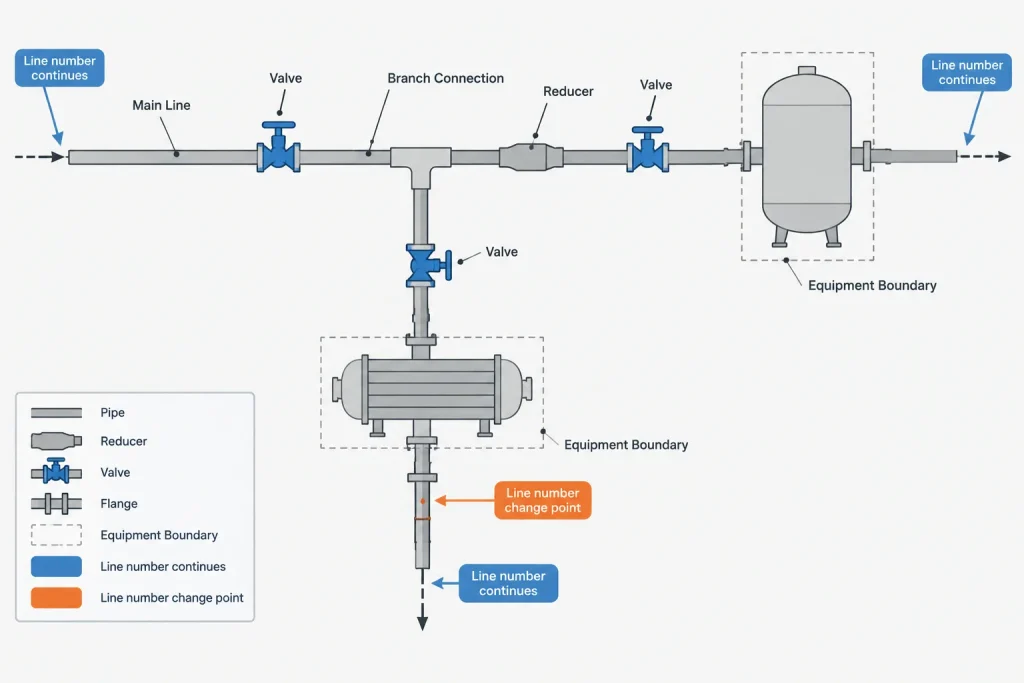
Reducers create an important project-specific question: does the line retain its identifier after a size change, or does the downstream section receive a new identifier? Some projects continue the same sequence and update the size field. Others establish a separate line designation. CAD data and drawings must follow the adopted rule consistently.
Service codes and sequence numbers
The service code communicates the process or utility function, but abbreviations are rarely safe to guess. The same letters can represent different services on different projects. Designers should check the approved abbreviation list, P&ID legend, or line-number procedure.
The sequence field provides uniqueness within the numbering system. It is not necessarily a physical routing order, equipment number, flow sequence, or drawing number. Unless the project procedure says otherwise, sequence values should be treated as identifiers rather than engineering data.
A line may continue through multiple drawings and model files without receiving a new sequence. Conversely, two pipes that appear adjacent in a model may have different identifiers because they serve different process functions or belong to separate engineering systems.
How the piping class affects interpretation
A piping class or material-class code often links the line to an approved component specification. That specification may govern permitted pipe materials, wall selections, fittings, flanges, valves, branch connections, gaskets, bolting, end preparations, and other construction details.
The class code is not the same thing as flange pressure class, pipe schedule, or material grade. Those properties may be controlled by the piping class, but they should not be treated as interchangeable labels.
If the material class changes along a route, the change should be documented at a defined boundary. The line number may change, gain a modifier, or remain the same while a separate class field changes. The correct method depends on the project data model. The important requirement is that the P&ID, line list, model, isometric, and bill of materials identify the same boundary.
Line-number changes at branches and equipment
A branch connection does not automatically require a new line number. The decision usually depends on whether the branch has a distinct function, size, destination, service condition, or class assignment under the project rules.
Equipment nozzles are also common line-number boundaries, but not every nozzle connection creates a new engineering line in the same way. A pipeline may run between equipment items, terminate at a nozzle, or continue logically through a packaged system. Ownership boundaries and vendor-package interfaces can affect the numbering method.
Do not create a new identifier merely because a route crosses a drawing match line, enters another CAD file, changes elevation, or passes through a fitting. Those are drafting or geometry events unless the project numbering procedure defines them as line boundaries.

A reliable decoding workflow
- Find the project legend. Confirm field order, separators, abbreviations, optional fields, and unit conventions.
- Check the line list. Use it to verify service, size, design conditions, material class, insulation, tracing, and other controlled attributes.
- Trace the P&ID. Follow the line through branches, equipment connections, valves, reducers, and specification breaks.
- Compare the CAD model. Confirm that connected components carry the intended line assignment and that boundaries occur at the correct locations.
- Review deliverables. Check isometric titles, line callouts, continuation notes, bills of material, and tie-in references for consistency.
- Resolve conflicts at the source. Do not silently edit one drawing to make it agree with another. Determine which controlled document or database should be corrected.
Managing line data in CAD
Where the CAD system supports object data, line-number fields should be stored as attributes rather than drawn only as disconnected text. Structured data makes it easier to generate isometrics, filter components, create reports, and detect mismatches.
It is still useful to separate the full displayed identifier into meaningful database properties. Size, service, sequence, class, insulation, and tracing may change under different rules. Storing only one combined text string can make revisions and validation more difficult.
Before splitting or merging modeled pipelines, confirm the effect on connected components and generated documents. A graphical break may unintentionally create a new data record, while a visually continuous route may conceal two sections with different class assignments.
Common reading and drafting errors
- Assuming the format matches a previous project.
- Reading the size field as actual outside or inside diameter.
- Treating the piping-class code as a flange rating or pipe schedule.
- Assigning a new line number at every branch, reducer, or drawing continuation.
- Leaving valves or fittings assigned to the wrong line after rerouting.
- Changing annotation text without updating the underlying model data.
- Allowing P&ID, line-list, model, and isometric identifiers to diverge.
- Using retired or duplicated sequence numbers without authorization.
Practical review questions
During a CAD or drawing review, ask whether the identifier is unique under the project rules, whether every field agrees with the line list, and whether all connected components belong to the intended line. Check size and class transitions at reducers, branches, equipment nozzles, tie-ins, and package boundaries.
A line number is most useful when it functions as a reliable data key rather than decorative annotation. Correct interpretation allows designers and reviewers to move confidently between process documents, piping specifications, CAD models, isometrics, material reports, and field records without confusing the pipeline identity with the individual parts used to build it.
Use the line number as a cross-document control
A line number should connect the same engineering identity across the P&ID, line list, piping model, isometric, material report, and related records. A matching text label alone does not prove that the underlying attributes are correct. The displayed callout and the structured CAD or database record should be reviewed together.
During revisions, distinguish a routing change from an engineering identity change. Moving a line or changing its elevation may affect geometry without changing its service or specification. A change to service, size, class, or a defined system boundary may require a different treatment under the project procedure. The numbering decision should follow that procedure rather than the appearance of the revised route.
Document the reason for each boundary
Line-number and class boundaries should occur for a deliberate project-defined reason. When a boundary is associated with a reducer, branch, equipment nozzle, tie-in, package interface, or specification break, the related documents should show the same transition. This makes the identifier useful for review, procurement, fabrication, construction, and recordkeeping.
Check data handoffs as well as graphics
- Confirm that connected valves, fittings, flanges, and branch components carry the intended line assignment.
- Check that line callouts agree with the properties used to generate isometrics and reports.
- Review continuation points so the identifier remains consistent across drawings and model files.
- Verify that obsolete identifiers are not left in annotation, object properties, report filters, or copied components.
- Resolve discrepancies through the project change process instead of editing isolated text to hide a conflict.
Frequently asked questions
Can a piping line number be decoded without the project legend?
Not reliably. A familiar field may suggest a service, size, sequence, or class, but only the project convention defines its intended meaning and format.
Does a line number identify every individual pipe component?
No. It generally identifies an engineering pipeline or a defined portion of one. Individual valves, instruments, spools, pieces, and welds may have separate identifiers for tracking and documentation.
Does a reducer always require a new line number?
No. Some project conventions retain the pipeline identity through a size change, while others assign a different designation. The line-number procedure and line list should control the decision.
Is the piping class the same as pipe schedule or flange pressure class?
No. A piping class may control or reference permitted component details, but its code should not be treated as another name for pipe schedule, flange pressure class, or material grade.
What should be done when the CAD model and line list disagree?
Do not guess or silently change a drawing label. Identify the project-controlled source, determine why the records differ, and correct the affected model data and deliverables through the established review process.
Should a designer edit the visible line-number text directly?
If the annotation is generated from structured data, the underlying attributes should be corrected so drawings, isometrics, and reports remain coordinated. Editing only the visible text can leave conflicting information elsewhere.