Tag: pid
-
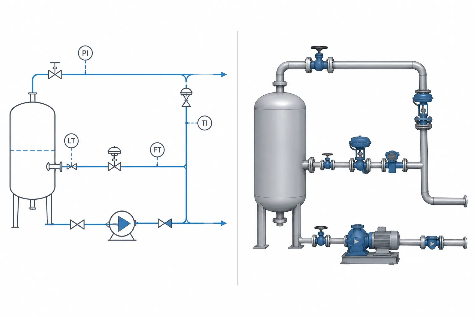
P&ID Symbols vs. 3D Piping Models: Why Functional Diagrams and Physical Geometry Differ
-
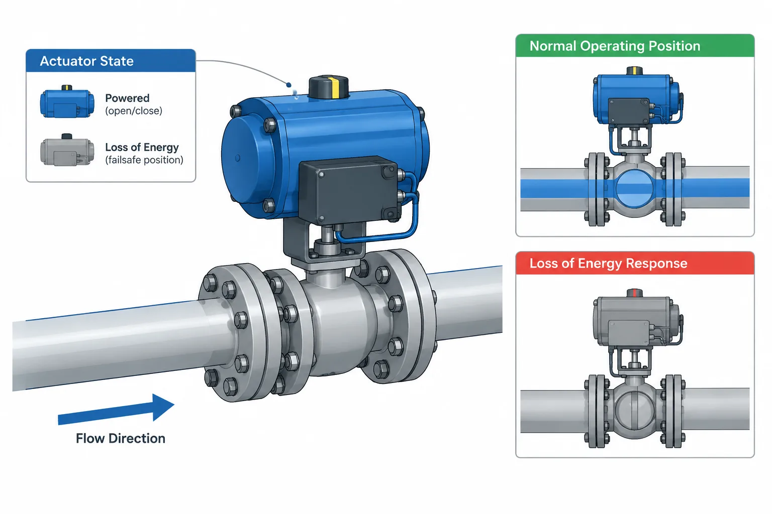
Valve Normal Position vs. Fail Position: How to Read and Document Operating States
-
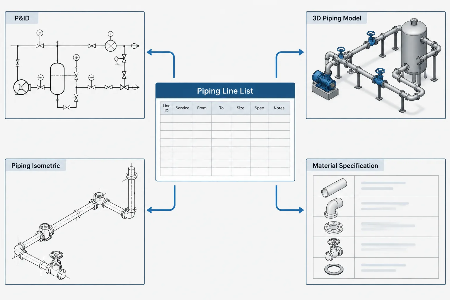
Piping Line List vs. P&ID, CAD Model, and Isometric: A Practical Data-Control Guide
-
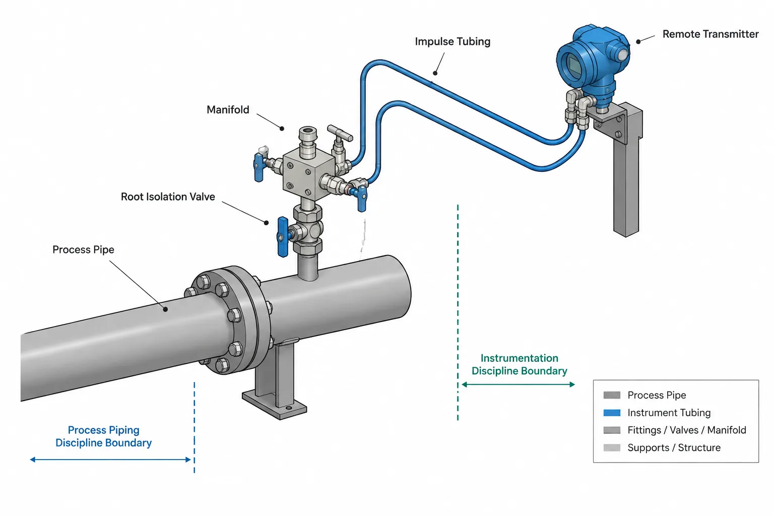
Instrument Connections in Piping CAD: Process Taps, Root Valves, and Model Boundaries
-
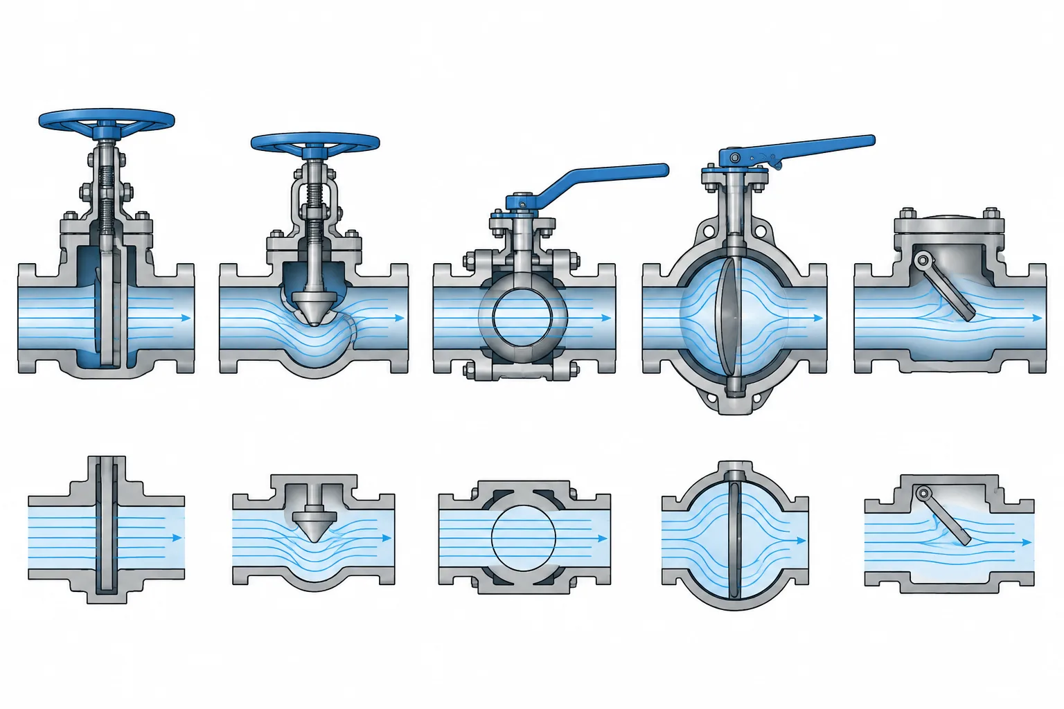
Valve Cv in Piping Documentation: Flow Coefficient, Valve Size, and CAD Data
-
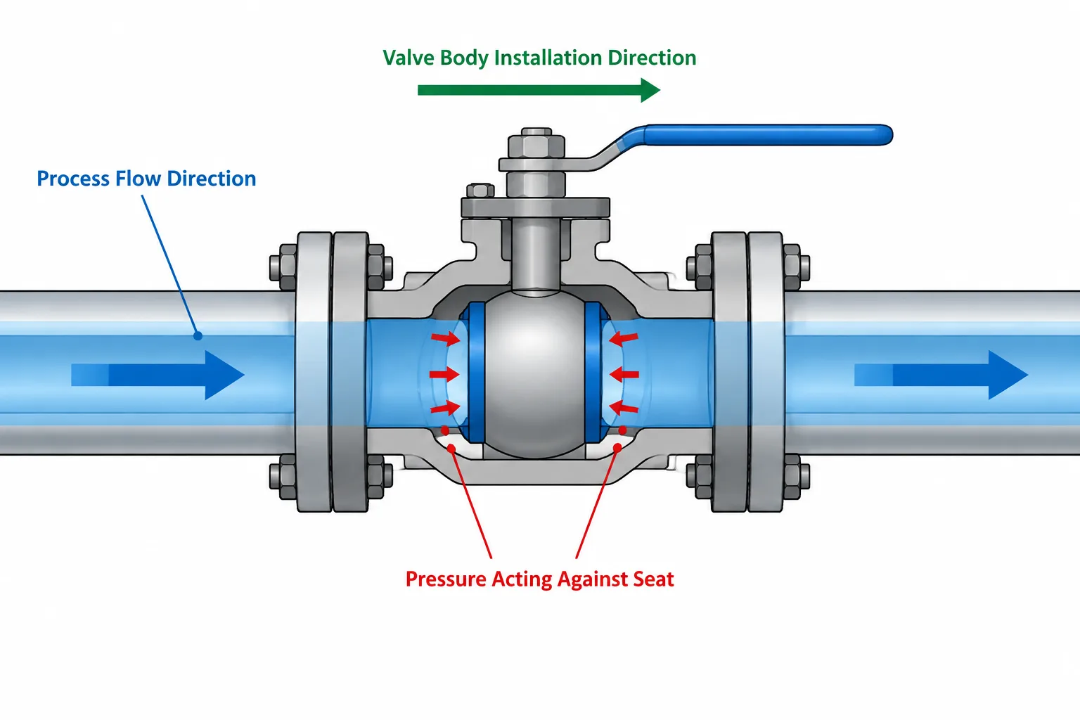
Directional vs. Bidirectional Valves in Piping CAD: Flow, Sealing, and Installation Control
-
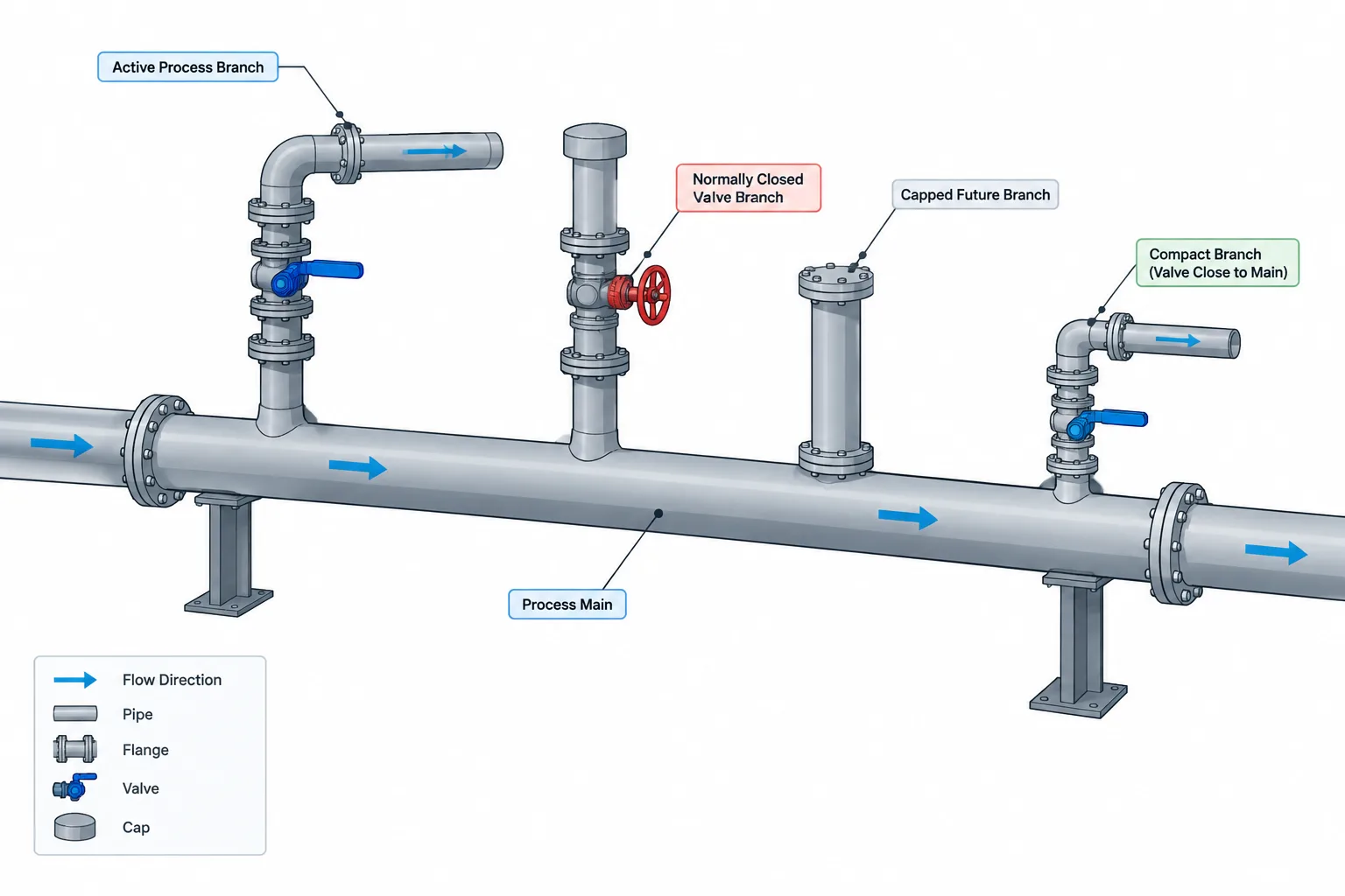
Dead Legs in Piping Layout: How to Identify, Measure, and Document Stagnant Branches
-
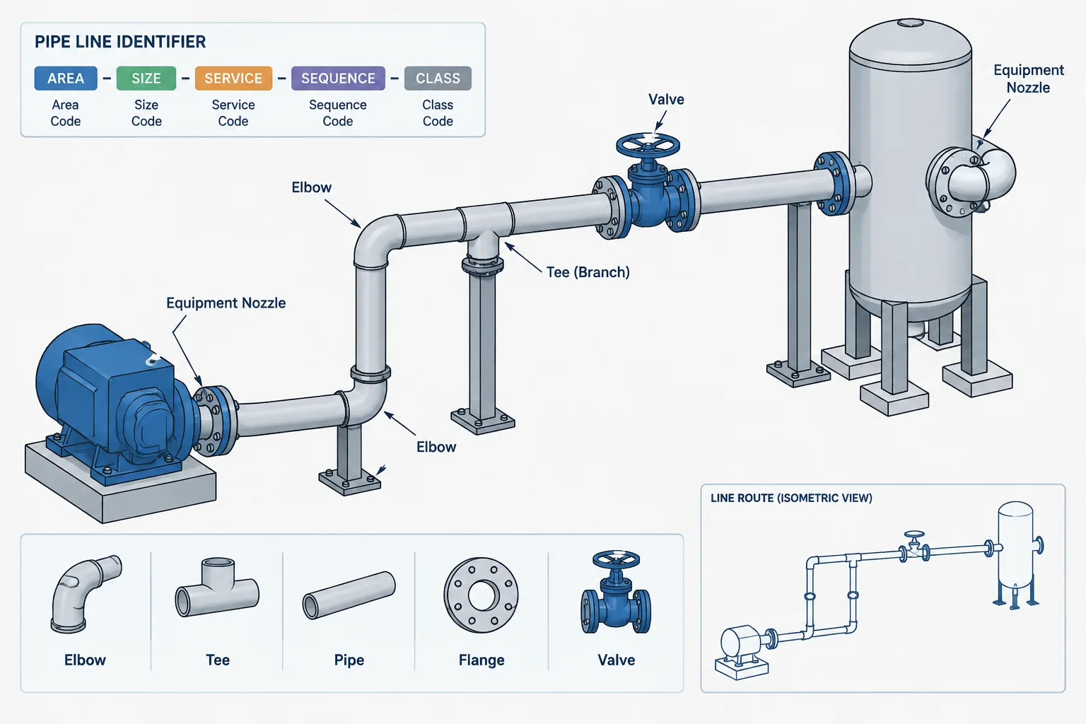
How to Read a Piping Line Number: Service, Size, Class, and Sequence
-
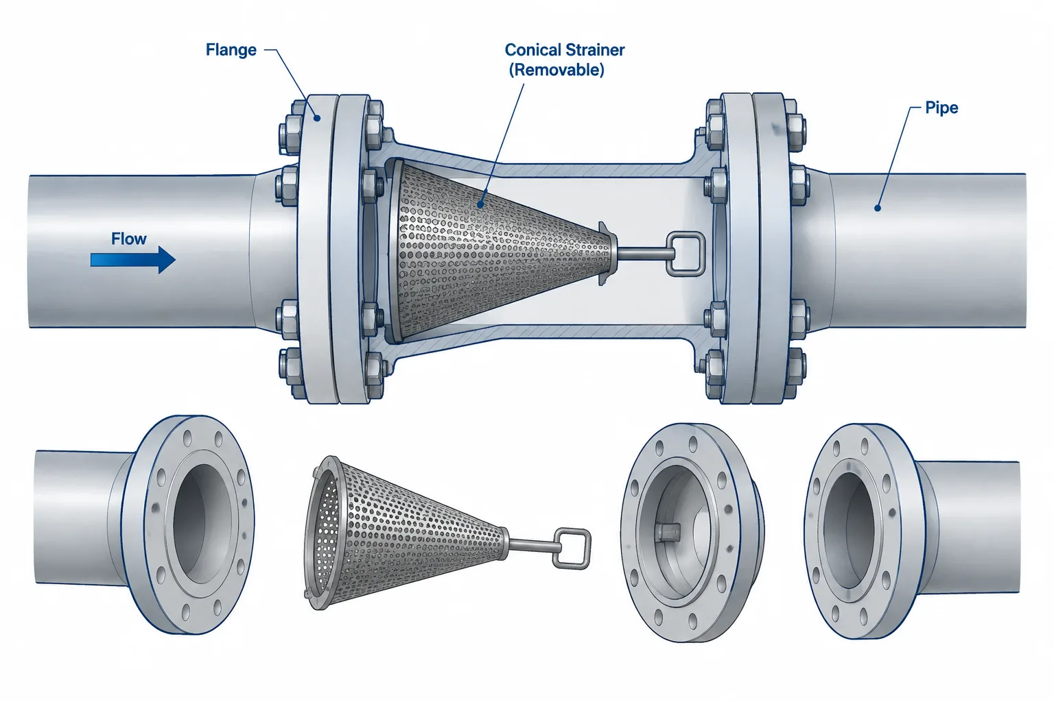
Temporary Strainers in Piping CAD: Placement, Orientation, and Removal Planning