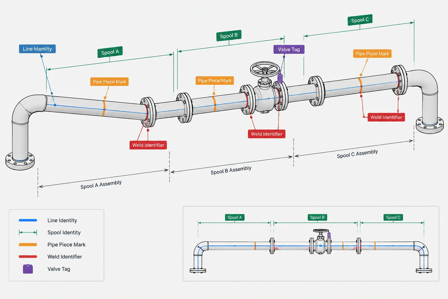
Piping drawings often place several identifiers around the same assembly, but each label answers a different question. The line number establishes the engineering identity, the spool number controls a fabricated assembly, and the piece mark identifies an item within the applicable fabrication system.
This guide explains how pipe spool numbers relate to line numbers, piece marks, weld IDs, component tags, and drawing numbers. It also shows why keeping these identifiers separate is important when coordinating CAD data, shop records, inspection documents, shipping information, and field installation.
A piping isometric may display several identifiers near the same piece of pipe: a line number, spool number, pipe piece mark, weld ID, and one or more component tags. Although these labels are related, they do not identify the same thing. Treating them as interchangeable can create errors in material tracking, fabrication status, drawing revisions, and field installation.
The exact naming system varies by company, fabricator, and project. Some organizations use spool number and spool piece number differently, while others use piece mark for both pipe segments and complete assemblies. The project identification procedure therefore remains the controlling reference. The practical distinction is based on what each identifier is intended to track.
The identification hierarchy
A useful way to understand piping identifiers is to move from the process system down to the individual fabricated item:
- Line number: identifies a pipeline or defined piping service within the engineering documentation.
- Spool number: identifies a transportable or installable fabricated assembly belonging to that line.
- Piece mark: identifies an individual cut pipe section, fitting, support item, or other fabrication piece, depending on project practice.
- Weld ID: identifies a specific welded joint for fabrication and inspection records.
- Component tag: identifies a particular tagged item such as a valve, instrument, specialty component, or equipment connection.
These identifiers form overlapping tracking systems rather than one universal numbering sequence. A spool can contain several pipe pieces, fittings, welds, and tagged components while still belonging to one line number.
What a line number identifies
The line number connects piping geometry to process and specification data. Its encoded or database-linked information may include service, nominal size, piping material class, insulation designation, or other project attributes. The format is project-specific and should not be decoded by assumption.
A single line number may continue through multiple drawings, model areas, and fabricated spools. Splitting that line into shop-manageable assemblies does not normally create a new process line. Conversely, one physical route should not be assumed to retain the same line number through every connection. A specification break, equipment boundary, package boundary, or process definition may require another line designation.
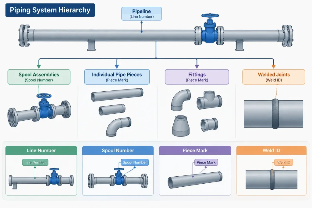
For CAD work, the line number is usually a system-level property. It should remain synchronized among the P&ID, line list, model, isometrics, and material reports. A spool number should not be used as a substitute where the engineering line identity is required.
What a spool number identifies
A pipe spool is a prefabricated assembly prepared for handling and installation as a unit. It can include pipe, fittings, flanges, branch connections, reinforcement, and sometimes valves or other components when permitted by the project fabrication plan.
The spool number provides assembly-level control. It may be used on:
- Spool fabrication drawings
- Shop production schedules
- Material issue records
- Coating and treatment records
- Inspection and release documentation
- Shipping manifests and storage plans
- Field erection sequences
Spool boundaries are commonly associated with field welds, flanged joints, threaded assembly points, or other planned breaks. However, every detachable connection is not automatically a spool boundary, and every drawing break is not a physical assembly break. The issued isometric and spool documentation must establish the actual limits.
Spool number versus isometric number
An isometric drawing number identifies a document. A spool number identifies a fabricated assembly. One isometric can show multiple spools, and a complex spool may require more than one drawing view or sheet. Keeping document identity separate from assembly identity allows a drawing to be revised without silently redefining the physical spool.
What a piece mark identifies
A piece mark usually tracks an individual fabrication item within a spool or work package. For straight pipe, it may connect a cut length to its material description and location in the assembly. For structural attachments or support fabrication, the same term may identify plates, shapes, clips, or other prepared items.
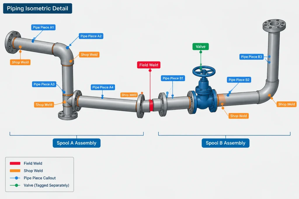
Piece-mark practices differ substantially. A fabrication system may assign marks only to cut pipe, while another may mark fittings, loose flanges, gaskets, or support elements. Before creating or interpreting a cut list, determine which item categories receive piece marks and whether marks are unique by spool, drawing, work package, or project.
Identical geometry does not always mean that two items should share a piece mark. Material heat traceability, end preparation, coating, orientation, branch location, or fabrication sequence may make apparently similar pieces distinct. CAD geometry alone may not contain enough information to consolidate them safely.
How the identifiers compare
| Identifier | Primary object | Main purpose | Typical scope |
|---|---|---|---|
| Line number | Pipeline or process service | Engineering and specification control | Across drawings and multiple spools |
| Spool number | Fabricated piping assembly | Shop, shipping, and erection tracking | One defined assembly |
| Piece mark | Individual fabrication item | Cutting, preparation, and assembly location | Within a defined numbering system |
| Weld ID | Specific joint | Welding and inspection traceability | One joint |
| Component tag | Functional or maintainable item | Engineering, operation, and asset identification | One tagged component |
| Drawing number | Controlled document | Revision and document management | One drawing or sheet set |
Do not confuse a piece mark with a component tag
A valve tag normally follows the valve through engineering, procurement, installation, commissioning, and operation. A piece mark is generally a fabrication identifier. If a tagged valve is installed in a spool, the spool drawing may show both identifiers, but they serve different users.
Replacing a tagged valve may preserve its functional tag even when the replacement item has a different procurement record. A fabricated pipe segment, by contrast, may receive a new piece mark when it is recut or remade. Combining these fields into one CAD attribute makes revision and replacement tracking difficult.
CAD data structure and drawing presentation
In an intelligent model, each identifier should have its own property field. Avoid storing a combined text string when downstream reports need separate values. A spool label may display the line and spool identifiers together for readability, but the underlying data should remain independently editable and reportable.
Drawing annotations should also make the hierarchy visually clear. Place the line number where it identifies the route, show spool limits at the applicable assembly breaks, attach weld IDs directly to joints, and associate piece marks with the items they identify. Leaders should not cross in a way that makes a weld number appear to label a fitting or pipe piece.
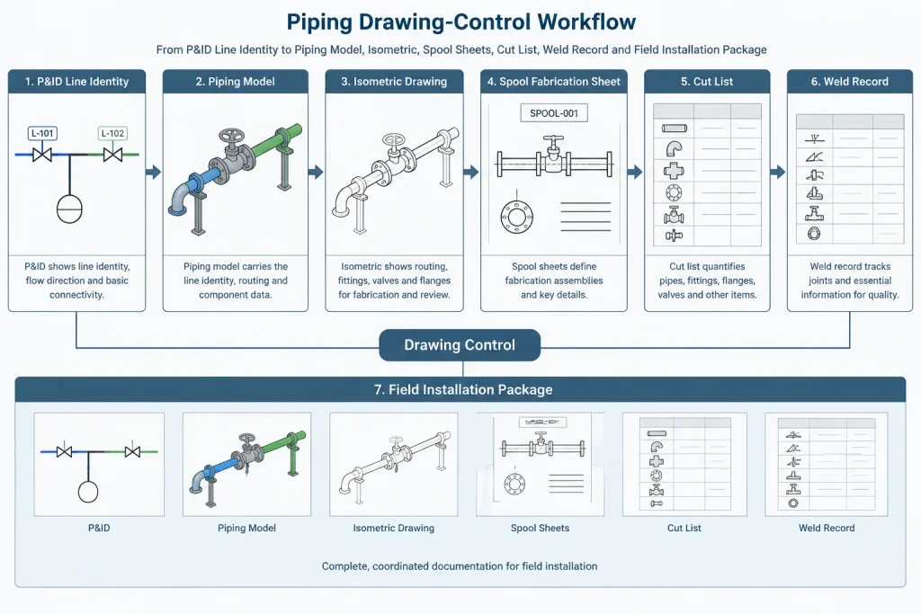
When a drawing is crowded, use a controlled table or cut list rather than removing essential identity information. A table can connect piece marks to descriptions, material requirements, end preparations, and cut-length fields without overloading the graphical view.
Revision effects that require special attention
A routing revision can affect several identification layers at once. Moving a field weld may change spool boundaries, pipe cut lengths, piece marks, weld records, and shipping assumptions without changing the line number. Adding a valve may preserve the line identity while requiring a component tag, new mating joints, and revised spool content.
Before retaining an existing spool number after a change, confirm whether the physical assembly is still considered the same controlled item. Project procedures may require a revision, suffix, cancellation, or new spool identity. Do not renumber automatically unless the numbering rules are known; uncontrolled renumbering can disconnect shop records from field material already produced.
A practical identification check
Before issuing an isometric or spool drawing, perform a trace from the system level to the individual joints:
- Confirm that the line number agrees with the current line list and model properties.
- Verify that every spool has clear physical boundaries.
- Check that spool numbers are unique within the required project scope.
- Confirm that piece marks point to the correct cut or fabricated items.
- Compare piece-mark data with the cut list and material description.
- Verify that every required weld has a distinct, readable weld ID.
- Keep valve and specialty-item tags separate from fabrication marks.
- Check that field welds, shop welds, and loose-shipped items are classified consistently.
- Review revision clouds and change records for effects on existing identifiers.
- Confirm that the drawing, model, material report, and fabrication package use the same released identification data.
Why the distinction matters
Clear identification allows different teams to discuss the same physical piping without ambiguity. Engineering can refer to the line, fabrication can track the spool and its pieces, quality personnel can locate a weld, and field crews can identify the assembly to install. The labels may appear together on one drawing, but each controls a different level of information.
The safest workflow is to preserve that separation in both CAD data and drawing annotations. When project terminology differs, document the local definitions explicitly rather than relying on familiar wording from another job.
How to resolve an identifier conflict
When identifiers disagree between a model, isometric, cut list, or fabrication record, first determine which type of object is being discussed. A discrepancy involving the pipeline identity is not resolved by changing a spool label, and a missing weld ID is not corrected by assigning a piece mark.
Trace the information from its controlling project record to each downstream document. Review the line list and released engineering data for the line identity, the approved spool package for assembly boundaries, the cut list for fabrication pieces, and the applicable welding or inspection record for joint identity. If the project procedure assigns control differently, follow that procedure rather than relying on the apparent meaning of a label.
Use identifier ownership to improve handoffs
A practical workflow assigns responsibility according to the object being controlled. Engineering maintains the system-level identity and specification relationships. Detailing and fabrication coordinate spool boundaries and piece marks. Quality personnel use weld IDs to connect joints with inspection records. Construction verifies that the delivered assembly, loose items, and field connections match the released installation information.
This separation does not prevent teams from displaying related identifiers together. It ensures that a change to one field does not unintentionally redefine another object. Combined drawing labels may support readability, but the underlying CAD and reporting fields should remain distinct.
Questions to ask before changing a label
- Does the proposed change affect a process line, a fabricated assembly, an individual piece, a joint, or a tagged component?
- Is the identifier controlled by engineering data, fabrication planning, inspection records, or document management?
- Has material already been cut, fabricated, inspected, shipped, or installed under the current identifier?
- Will the change remain synchronized across the model, drawing, report, and released work package?
- Does the project procedure require a revision, replacement identity, cancellation, or retained identifier?
Answering these questions before editing the drawing helps preserve traceability and prevents a graphical cleanup from becoming an uncontrolled fabrication or field change.
Frequently asked questions
Is a spool number the same as a line number?
No. A line number identifies a pipeline or defined service within the engineering documentation. A spool number identifies a fabricated assembly that belongs to the applicable line.
Can one line number include multiple pipe spools?
Yes. A line can continue through multiple fabricated assemblies, drawings, or model areas. Dividing it into spools does not by itself create separate process lines.
Is a piece mark always assigned only to straight pipe?
No. The meaning depends on the project or fabricator. Piece marks may identify cut pipe, fittings, support items, attachments, or other prepared components. The governing identification procedure defines the applicable scope.
Can a spool number be used as an isometric drawing number?
They should be treated as separate identifiers. The drawing number controls a document, while the spool number controls a physical assembly. They may appear together but should remain independently managed.
Why does a weld need its own ID?
A weld ID connects a specific joint with fabrication and inspection information. A piece mark identifies an item, and a spool number identifies an assembly, so neither provides the same joint-level traceability.
Should identical pipe pieces share a piece mark?
Not automatically. Differences in material traceability, end preparation, coating, orientation, branch position, or fabrication sequence may require separate identities even when the visible geometry appears alike.
What should happen when a revision moves a spool boundary?
Review the effects on spool identity, piece marks, weld records, cut information, and existing shop or field records. Apply the project revision and numbering procedure rather than renumbering the affected items by assumption.