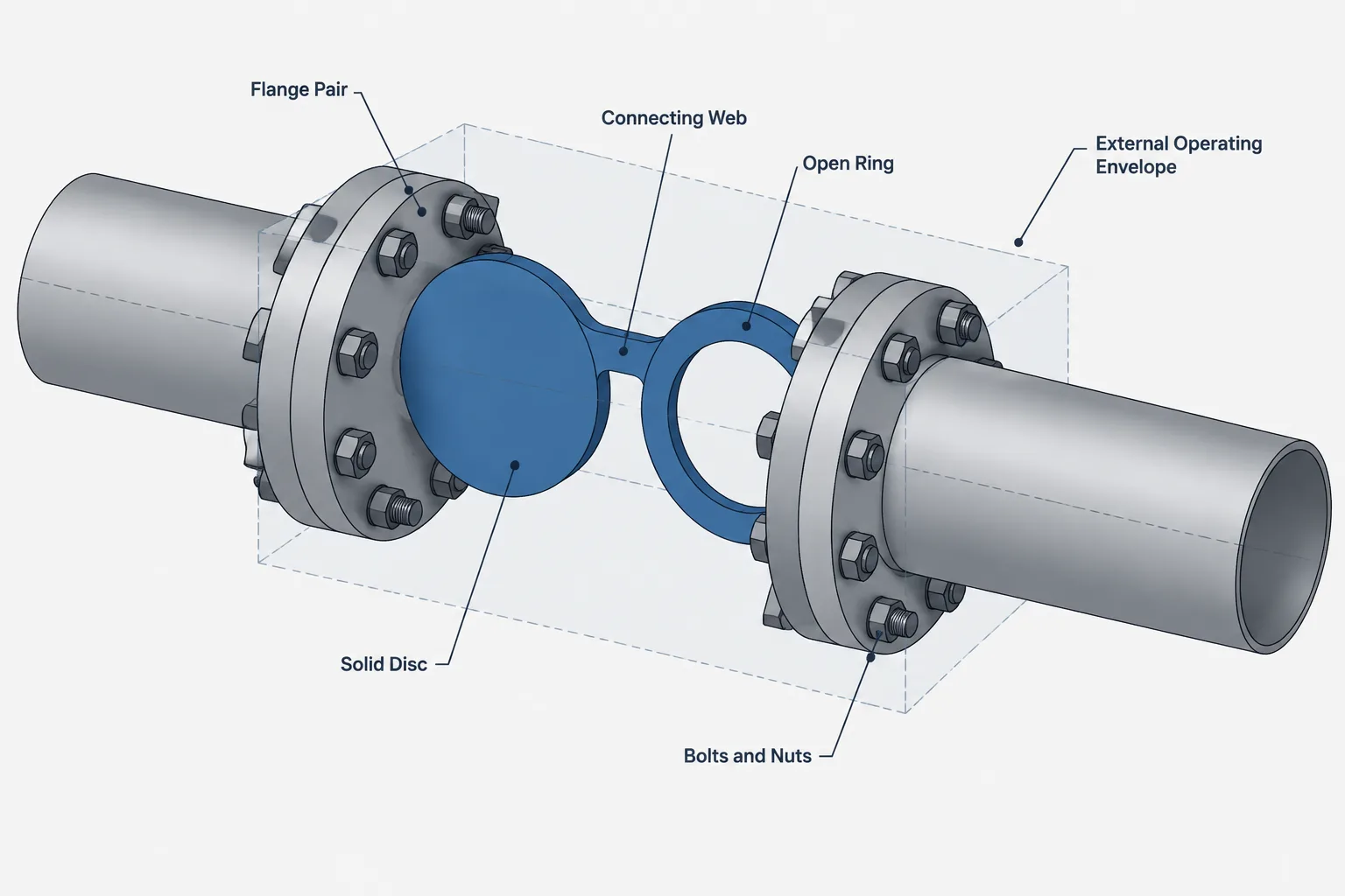
Spectacle blinds, spades, and spacers must be represented as functional parts of a flanged joint, not merely as simple CAD shapes. Their selected condition affects isolation status, assembly geometry, access, documentation, and the space required for operation.
This guide explains how to distinguish these components, document whether the flow path is open or blocked, coordinate the flange-joint stack, and review movement and withdrawal clearances. Final geometry and assembly details should always be based on approved project specifications and verified component data.
Spectacle blinds, spades, and spacers provide a visible means of changing a flanged piping connection between open and blocked conditions. Although their geometry is simple, they affect flange spacing, bolting, maintenance access, operating procedures, and drawing status. Treating one as a generic plate between flanges can therefore create problems in both CAD models and fabrication documents.
The essential drafting question is not only which component is installed. The model and associated documents must also communicate its current or intended position, how the joint is assembled, and whether enough space exists to operate or remove it safely. Those details should be coordinated with the project piping specification, isolation philosophy, operating procedure, and approved component data.
What the Terms Mean
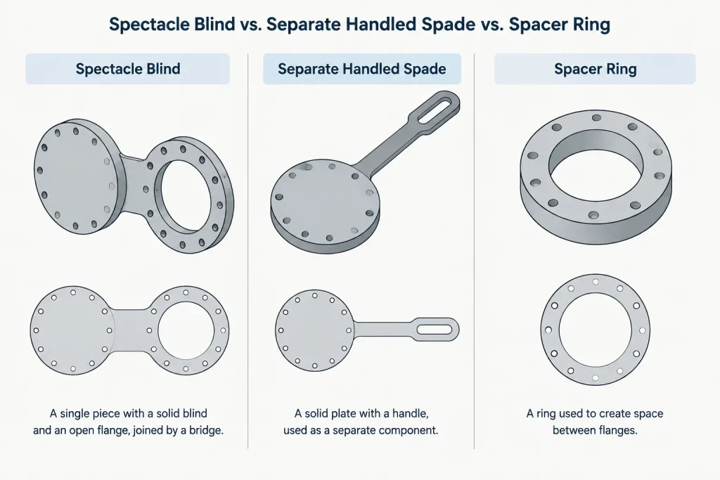
These components are related, but they are not interchangeable names for the same item.
| Component | Basic form | How the line condition changes | Important CAD implication |
|---|---|---|---|
| Spectacle blind | A connected solid plate and open ring, commonly arranged in a figure-eight form | The assembly is repositioned so either the solid side or open side lies between the flanges | The model should account for both positions and the clearance needed to swing or reposition the assembly |
| Spade | A separate solid plate, often with an external handle or identification tab | The spade is inserted to block the line and removed to reopen it | Removal space, handling space, and storage of the loose component may matter |
| Spacer | A separate open ring intended to occupy the joint when the spade is removed | The spacer replaces the spade in the open condition | The spacer maintains the planned joint arrangement rather than leaving an unaccounted gap |
A spectacle blind combines the blocking and spacing functions into one connected assembly. A spade-and-spacer arrangement uses two separate pieces. In both cases, the external shape or handle helps personnel identify which condition is present without relying only on process indications.
Terminology varies among owners, fabricators, and suppliers. Terms such as line blind, paddle blind, skillet blind, and figure-eight blind may appear in project documents. The component description, drawing symbol, and purchasing terminology should be reconciled instead of assuming that every local name has an identical meaning.
Why These Components Are Not Blind Flanges
A blind flange closes the end of a flanged line or nozzle and is bolted as one side of the joint. A spectacle blind or spade is an insert located between two mating flanges. That distinction changes the joint geometry and the way the component is operated.
Replacing an inserted blind with a blind flange in a CAD model can misrepresent the number of flanges, gasket locations, bolt arrangement, and overall face-to-face stack. It can also obscure the operational intent. A blind flange usually represents an end closure, while an inserted blind commonly represents a selectable isolation point within a line.
Likewise, a solid plate should not be modeled as an arbitrary sheet cut to the pipe outside diameter. Its pressure-containing dimensions, material, facing contact, identification, and suitability for the service must come from approved project or supplier data.
Open and Closed Position Must Be Explicit
A spectacle blind has two physical states. In the open state, the ring portion aligns with the pipe bore. In the closed state, the solid portion blocks the flow path. A separate spade-and-spacer set achieves the same basic change by exchanging components.
The CAD model should not leave that status to visual interpretation alone. A thin solid and an open ring may be difficult to distinguish in plan views, congested models, or low-detail exports. Use an attribute, property, annotation, or controlled model state such as:
- Normally open or normally closed, when defined by project terminology
- Open side installed or blind side installed
- Spade installed or spacer installed
- Operating position, maintenance position, or shutdown position
- Status pending confirmation, when the design condition is unresolved
Do not infer the required operating state solely from a generic P&ID symbol. The P&ID may communicate isolation intent without depicting the physical orientation of the installed hardware. Confirm the intended condition against the line blind list, operating documentation, marked-up drawings, and project procedures.
Model the Complete Flange Joint Stack
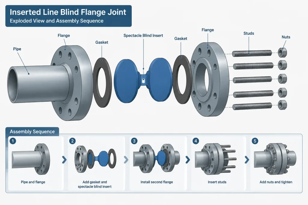
An inserted blind affects more than the visible plate. The joint may include two flanges, the blind or spacer, gasket interfaces, studs or bolts, nuts, and any project-specific accessories. The exact assembly depends on the selected component and approved joint design.
For layout work, the CAD model should carry enough information to control the distance between flange faces and the resulting connected pipe lengths. For fabrication or bolt takeoff work, generic thickness assumptions are not adequate. Obtain the applicable component thickness, gasket arrangement, and bolting requirements from verified data.
A useful model separates the following properties:
- Nominal pipe size and applicable flange designation
- Component type: spectacle blind, spade, or spacer
- Material or piping class association
- Installed position or status
- Insert thickness used in the joint stack
- External envelope and handle orientation
- Component tag or blind-list identifier
Keeping status separate from component type prevents a common data error. A spectacle blind remains a spectacle blind whether its open or solid side is installed; only its position changes.
Allow Space to Operate the Blind
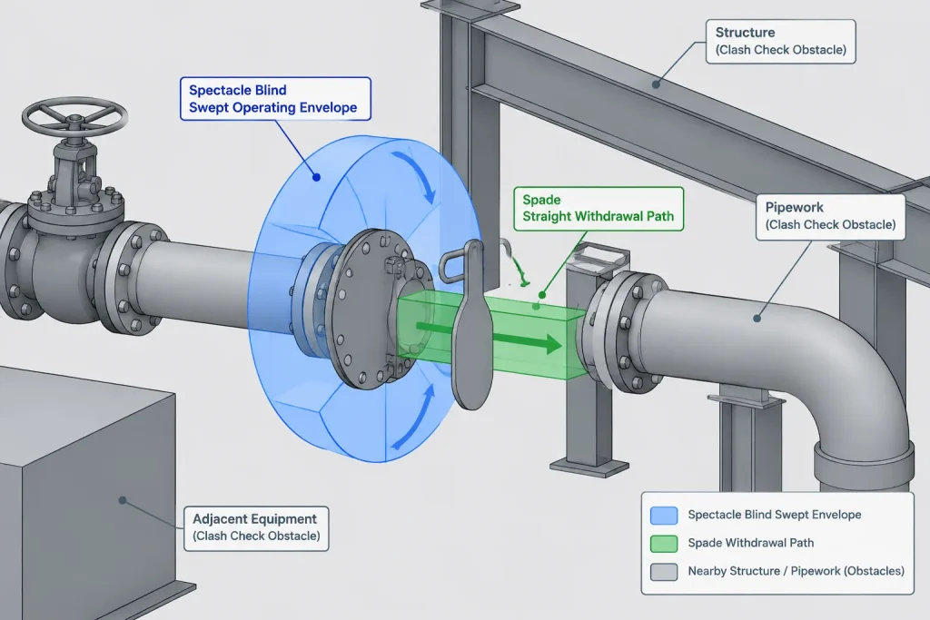
A line blind that fits geometrically in its installed position may still be impossible to operate. Changing position generally requires loosening the joint, separating the flange faces sufficiently for movement, handling the component, and retightening the assembly under an approved procedure. The required work envelope can be much larger than the component shown in its normal position.
Swing clearance for spectacle blinds
Check the swept envelope of the unused half as the assembly is repositioned. Nearby pipe, structural steel, cable tray, insulation, valve operators, platforms, and handrails can block this path. The connecting web and pivot arrangement should be based on the actual selected design rather than a generic rotation assumption.
Withdrawal clearance for spades and spacers
A separate spade or spacer needs a clear extraction path. Confirm that the handle can pass surrounding objects and that personnel have room to support the loose piece. For large or heavy items, the layout may also need to accommodate project-defined lifting or handling provisions.
Flange separation and pipe flexibility
The presence of an external gap in the model does not prove that the real flanges can be spread safely. Pipe stiffness, supports, anchors, equipment nozzles, and nearby connections influence movement. CAD should identify the spatial need, but engineering and the approved isolation procedure must determine how the joint may be opened.
Orientation and Visibility
The external portion should be oriented where it can be seen and reached. Avoid placing the handle or unused spectacle half inside insulation, against a wall, beneath an inaccessible platform, or in conflict with a support.
Orientation may also affect drainage, dirt accumulation, personnel exposure, and lifting access. There is no universally correct clock position for every installation. Select it through layout review and record it when orientation is important to operation or constructability.
If insulation surrounds the line, model or show the relationship between the insulation envelope and the projecting blind feature. Removable insulation or a local termination detail may be needed, but it should not be invented by the drafter without project direction.
Drawing and Data Coordination
Different documents may describe the same isolation point at different levels of detail. The P&ID establishes process intent; the piping model establishes location and physical arrangement; the isometric controls fabrication and assembly information; and the blind list or operating record tracks identification and status.
A coordinated documentation set should answer these questions:
- Where is the isolation point?
- Which physical component type is required?
- What is its unique identifier, if the project uses one?
- Which side or piece is installed in the documented condition?
- Does the isometric show the correct joint stack and bill-of-material item?
- Can the component be operated without a clash?
- Is the shown status a design baseline, an operating condition, or a temporary shutdown condition?
Temporary status changes should not be allowed to overwrite the permanent design basis without controlled revision. A model used for normal operation may need a separate view, configuration, or markup to communicate a turnaround isolation plan.
Practical CAD Review Workflow
- Confirm the isolation intent. Review the process documents and project terminology before choosing a component.
- Select verified geometry. Use approved manufacturer or project data for thickness, outside profile, and connection details.
- Build the joint stack. Coordinate flange faces, insert, gaskets, bolting, and adjacent pipe lengths.
- Set the documented position. Record open, closed, spade installed, or spacer installed as a controlled property.
- Check the operating envelope. Test swing, withdrawal, flange-access, and handling clearances.
- Review orientation. Confirm visibility, accessibility, insulation treatment, and conflicts with supports or structure.
- Synchronize deliverables. Compare the model, isometric, bill of material, P&ID reference, and blind list.
- Flag unresolved conditions. Do not hide unknown status or unverified dimensions behind generic CAD geometry.
Common Drafting Errors
- Using a blind flange symbol for an inserted spade or spectacle blind
- Showing the component but omitting its open or closed status
- Changing the graphical position without updating the component property or blind list
- Ignoring the insert when calculating flange spacing or connected pipe lengths
- Modeling only the installed envelope and not the operating clearance
- Placing the handle where insulation, steel, or another line blocks access
- Assuming generic bolting remains valid after the joint stack changes
- Using an unverified plate thickness as fabrication information
A Small Component With Large Documentation Consequences
Spectacle blinds, spades, and spacers are straightforward only when viewed as symbols. In an actual piping layout, they are operable parts of a flanged assembly and controlled isolation points. A reliable CAD representation combines verified joint geometry with clear status, orientation, access, and document coordination.
The best model does not merely show a plate between flanges. It tells designers, fabricators, operators, and reviewers what is installed, which condition is represented, and whether the arrangement can be assembled and changed as intended.
Using the CAD Model as a Controlled Isolation Reference
A useful model distinguishes permanent component identity from changeable operating status. The component record can identify a spectacle blind, spade, or spacer, while a separate property records the condition represented in the current model or drawing. This separation reduces the risk of changing graphics without updating schedules, isometrics, or operating records.
Reviewers should also distinguish a geometric clash check from an operability review. A component may fit between adjacent objects while installed but still lack sufficient room for flange access, repositioning, withdrawal, handling, or temporary support. These activities depend on the selected hardware and approved work procedure, so a clear model envelope should not be treated as authorization to open the joint.
Information That Requires Project Confirmation
Generic CAD content can support early layout, but it should clearly identify unresolved information. Before geometry is used for fabrication, procurement, bolting, or connected pipe-length calculations, confirm the following:
- The project-approved component type and naming convention
- The piping class or material association
- The verified insert geometry and joint arrangement
- The documented open or blocked condition
- The handle or external-feature orientation
- The applicable identification or blind-list reference
- The required operating, withdrawal, and maintenance envelope
- The relationship to insulation, supports, structure, and nearby equipment
Where information remains unknown, a visible review note or controlled status is preferable to geometry that appears complete but is based on assumptions.
Deliverable Review Perspective
Each deliverable answers a different question. Process documentation establishes the intended isolation function, the piping model controls physical arrangement, the isometric communicates assembly information, and the blind list or operating record identifies the tracked isolation point and its documented condition. Consistent identifiers and status terminology help reviewers recognize when these documents disagree.
Supplier terminology may differ from project terminology. Procurement descriptions, model properties, drawing notes, and bills of material should therefore refer to the same physical item and condition rather than relying on a local nickname alone.
Frequently Asked Questions
Can a generic spectacle blind CAD block be used for layout?
It can serve as a preliminary placeholder if its unverified status is clear. It should not control flange spacing, fabrication, bolting, or operating clearance until its geometry has been checked against approved project or supplier data.
Should open or closed status be part of the component name?
Component type and installed condition are better maintained as separate properties. A spectacle blind does not become a different component when repositioned, but its represented isolation status does change.
Why must a spacer be shown when the spade is removed?
The spacer represents the open-flow component intended to occupy the joint in a spade-and-spacer arrangement. Omitting it can misrepresent the flange stack, assembly condition, and required joint spacing.
Is a clash-free installed model sufficient?
No. The review should also consider access to the fasteners, movement of the spectacle assembly, withdrawal of a loose spade or spacer, handling space, insulation, and surrounding obstructions.
Can a spectacle blind be represented as a blind flange?
No. A blind flange closes an end as one side of a flanged connection, while a spectacle blind is inserted between mating flanges. Substituting one representation for the other can misstate the joint arrangement and isolation function.
Which document controls the operating position?
The answer depends on the project’s document-control and operating practices. The model, process documentation, isometric, blind list, and operating records should be coordinated, and discrepancies should be resolved rather than inferred from a generic symbol.