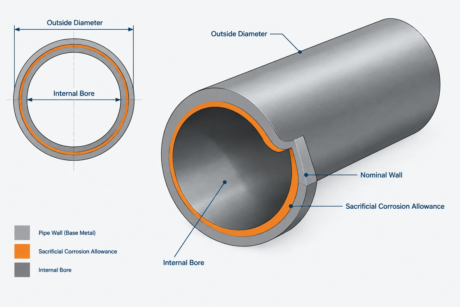
Corrosion allowance in piping connects several activities that are often managed in different places: wall-thickness calculation, pipe schedule selection, material specification, CAD modeling, procurement, and inspection planning. Problems arise when the allowance is mistaken for a physical coating, a dimensional addition, or a property that can be determined from schedule alone.
This guide explains how to keep the design reserve separate from nominal pipe geometry and manufacturing variation. It is intended to help engineers, designers, and drafters understand what the selected wall represents, where corrosion-related data should be controlled, and what must remain consistent when piping data moves between calculations and CAD systems.
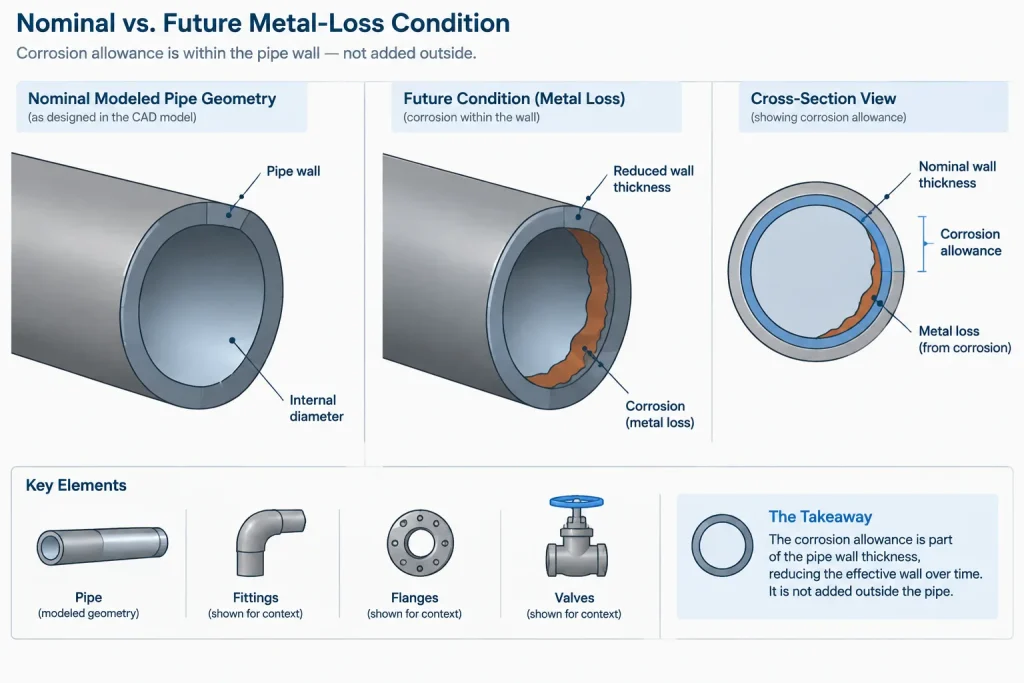
Corrosion allowance is extra material included in a piping wall-thickness selection to account for anticipated metal loss during service. The concept sounds simple, but it is often misunderstood in drawings and CAD databases. Corrosion allowance is not a separate layer added to the outside of a pipe, and it does not normally change the standardized outside diameter. It is a design input used when determining whether a selected pipe wall is adequate for the intended service life and design conditions.
For designers and drafters, the main challenge is knowing where corrosion allowance belongs in the project data. It may affect pipe schedule selection, branch calculations, fitting requirements, component descriptions, line lists, and mechanical calculations. It usually does not require modeling a second cylindrical surface or reducing the displayed pipe bore to a predicted end-of-life condition.
What corrosion allowance represents
Many piping materials gradually lose wall thickness when exposed to a process fluid, the surrounding environment, or both. The expected loss may result from general corrosion, erosion-corrosion, or another recognized degradation mechanism. A corrosion allowance reserves part of the initial metal thickness for that anticipated loss.
The allowance is generally associated with expected uniform or broadly distributed loss. It should not be treated as a universal solution for localized damage such as pitting, cracking, crevice attack, galvanic effects, or severe erosion. Those mechanisms may require material changes, linings, coatings, process controls, inspection plans, geometry changes, or other engineering measures.
Corrosion allowance is also not a prediction that every location will lose exactly the stated amount of metal. It is an engineering provision established through the project design basis, piping specification, materials review, owner practice, or applicable calculation procedure.
How it fits into wall-thickness selection
A piping engineer normally begins with a required structural wall based on the governing design method and applicable loads. Additional allowances are then considered as required. The selected nominal wall must be sufficient after the applicable deductions and manufacturing considerations are addressed.
A simplified conceptual relationship is:

Selected nominal wall must cover the required structural wall, applicable metal-loss allowance, mechanical allowances, and relevant manufacturing tolerance.
This is a concept rather than a substitute for a code calculation. The precise sequence, definitions, and acceptance rules depend on the governing code, component standard, project specification, material form, and service.
Required structural wall
This is the wall needed to resist the design conditions and other applicable loads. Pressure is an important input, but it may not be the only consideration. External pressure, bending, cyclic service, loads at branches, and other design effects may also require evaluation.
Corrosion or erosion allowance
This is the sacrificial portion associated with expected service-related wall loss. Different piping services in the same facility can have different allowances, even when they use the same nominal size or material.
Mechanical allowances
Threads, grooves, machining, forming, or similar operations can remove or redistribute material. Where relevant, their effect must be handled according to the applicable design and component rules. A corrosion allowance should not automatically be assumed to cover these separate effects.
Manufacturing tolerance
Commercial pipe is purchased by a nominal wall designation, but its permitted delivered wall may vary within the limits applicable to the product specification. A wall-thickness calculation therefore cannot always compare the calculated requirement directly with the nominal schedule wall and stop there. The applicable negative wall tolerance or other product-specific consideration must be addressed by engineering.
Corrosion allowance is not the same as mill tolerance
| Term | What it represents | How it is used |
|---|---|---|
| Corrosion allowance | Material reserved for anticipated service-related metal loss | Included in design and specification decisions |
| Nominal wall thickness | The designated wall associated with the selected pipe size and schedule or wall series | Used for procurement, dimensions, weight data, and CAD geometry |
| Manufacturing tolerance | Permitted variation in the delivered product relative to its nominal dimension | Considered when confirming that the selected nominal product is adequate |
| Measured wall thickness | The wall found at a particular location by inspection | Used for receiving inspection, condition monitoring, and remaining-life assessments |
Combining corrosion allowance and mill tolerance into one unlabeled value creates confusion. One addresses future service loss; the other addresses permitted variation in the manufactured product. They should remain distinguishable in calculations and controlled data.
Relationship to pipe schedule
Pipe schedule is a nominal wall-thickness series, not a corrosion rating. Selecting a heavier schedule may provide additional wall, but the schedule itself does not state how much of that wall is available for corrosion.
For a given nominal pipe size, the engineering workflow is generally to determine the required wall, apply the relevant allowances and tolerance treatment, and then select an available nominal wall that satisfies the result. The selected schedule may be thicker than the calculated minimum because commercial wall choices are discrete rather than continuously variable.
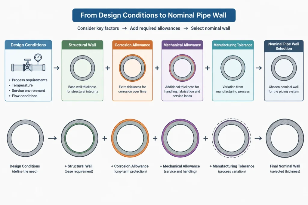
The same schedule can therefore be acceptable for one service and unsuitable for another. Conversely, two lines with different corrosion allowances may still end up using the same schedule because both calculated requirements fall within the capacity of that nominal wall.
Effect on outside diameter and inside diameter
For standard pipe sizes, changing schedule generally changes wall thickness inward while the standardized outside diameter remains associated with the nominal pipe size. A heavier wall therefore produces a smaller nominal bore.
Corrosion allowance does not normally create a larger modeled outside diameter. It is contained within the selected metal wall. If engineering selects a heavier schedule to accommodate an allowance, the CAD component should use the outside diameter and nominal wall corresponding to that selected pipe product.
The initial nominal inside diameter can be estimated from the nominal outside diameter and nominal wall, but it should not be confused with an exact manufactured bore. Actual dimensions can vary, and fittings, valves, lined components, and weld preparations may have different internal geometry.
An end-of-life corroded bore is generally not the default geometry for plant layout. If process or hydraulic analysis needs an aged internal diameter or roughness condition, that should be managed as a clearly identified analysis case rather than silently substituted for the nominal CAD bore.
Where the allowance should appear in project data
Corrosion allowance is commonly controlled in engineering data rather than graphical geometry. Depending on the project workflow, relevant locations may include:
- The piping material class or specification.
- The line list or associated line-design data.
- Wall-thickness calculation records.
- Branch reinforcement calculations.
- Equipment nozzle and piping interface reviews.
- Special-item datasheets where metal loss affects selection.
- Inspection and integrity-management records.
A general arrangement or isometric may show the selected schedule without displaying the corrosion allowance as a routine dimension. If the allowance is important to fabrication, procurement, inspection, or a special detail, it should be communicated through an approved note, data field, specification reference, or calculation link rather than inferred from the modeled wall.
CAD and database workflow
A reliable piping CAD workflow separates physical product geometry from engineering design criteria. The pipe object can store nominal size, selected schedule or wall designation, material class, and nominal dimensions. Corrosion allowance can be maintained as a separate controlled property when the software and project data model support it.
This separation prevents several common errors:
- Adding the allowance to the outside radius and creating a nonstandard pipe envelope.
- Subtracting the allowance twice when calculating or displaying the bore.
- Assuming every component in a line has the same available sacrificial wall.
- Changing schedule in the model without updating the specification, bill of material, or calculations.
- Treating a nominal CAD solid as a representation of measured as-built wall thickness.
Automated schedule selection should not be assumed unless the project system is explicitly configured, validated, and controlled for that purpose. In many workflows, engineering selects the wall and the CAD system represents the approved result.
Components need individual attention
A line-level corrosion allowance does not mean that every valve, flange, fitting, branch connection, or specialty item can be evaluated by subtracting that amount from a catalog wall. Components can have different design rules, shapes, minimum sections, bore transitions, and manufacturer-controlled dimensions.
Castings, forgings, fabricated branches, and formed fittings should be evaluated using the requirements applicable to those products. A valve body cannot be qualified merely because its connected pipe has a certain schedule. Likewise, a flange rating designation does not directly reveal a corrosion allowance.
For internally lined or clad systems, the project must distinguish between a metallic corrosion allowance and a separate corrosion-resistant barrier. The liner or cladding may serve a different function and may have different inspection, fabrication, and failure considerations.
Practical review checklist
- Confirm that the corrosion allowance comes from controlled project or engineering data.
- Verify that it has been included in the wall-selection calculation using the correct method.
- Keep corrosion allowance, mechanical allowance, and manufacturing tolerance distinct.
- Model the selected nominal pipe geometry rather than an invented allowance envelope.
- Check that schedule changes propagate to specifications, material reports, isometrics, and bills of material.
- Do not assume that pipe, fittings, valves, and flanges use identical adequacy checks.
- Identify whether hydraulic studies use initial, nominal, or aged internal conditions.
- Preserve calculated requirements and selection decisions outside the CAD geometry.
The key distinction
Corrosion allowance is a design reserve within the selected material thickness. Pipe schedule is the commercial nominal wall selected to help satisfy the engineering requirement. Mill tolerance describes permitted manufacturing variation, while CAD geometry normally represents nominal product dimensions. Keeping those four ideas separate makes wall-thickness decisions easier to calculate, model, procure, review, and maintain throughout the piping lifecycle.
Managing the engineering-to-CAD handoff
The most reliable handoff records both the engineering requirement and the product selected to satisfy it. The calculation establishes the required basis, while the piping specification and model identify the approved nominal component. Preserving both parts allows reviewers to understand why a schedule was selected without treating the CAD solid as the calculation record.
Keep design criteria traceable
A corrosion allowance should be traceable to controlled project data. If the design basis changes, engineering should reassess the affected wall selections and components rather than editing only a model property or drawing note. The revised decision should then flow through the applicable specification, line data, material output, and supporting calculations.
Keep nominal geometry consistent
The CAD model should normally use the dimensions associated with the selected nominal product. Display geometry, component metadata, isometrics, and material reports should agree on the approved wall or schedule designation. A separate corrosion-allowance field can support checking and data exchange, but it should not independently alter geometry unless the project has a documented workflow for doing so.
Identify the condition represented by analysis data
Hydraulic, mechanical, and integrity evaluations may not use the same wall or bore condition. Any dataset representing nominal, expected service, or measured condition should be clearly identified. This prevents an analysis assumption from being mistaken for procurement geometry or as-built inspection data.
Treat discrepancies as controlled changes
If a calculation, line list, piping class, and CAD model do not agree, the schedule should not be inferred from whichever source is easiest to edit. The discrepancy should be resolved against the project authority for that data, followed by coordinated updates to affected deliverables. This is especially important when a wall change influences connected components, branch evaluations, material quantities, or bore-dependent analysis.
Frequently asked questions
Can corrosion allowance be determined from pipe schedule?
No. Schedule identifies a nominal wall series, while corrosion allowance is a design input. The portion of the selected wall available for anticipated metal loss depends on the complete engineering evaluation.
Should corrosion allowance be subtracted from the bore shown in CAD?
Not in the normal nominal-product model. CAD geometry generally represents the selected pipe wall and resulting nominal bore. An aged or reduced-wall condition should be handled as a clearly identified analysis or integrity case rather than silently replacing the nominal geometry.
Does one line-level allowance apply to every connected component in the same way?
No. Pipe, fittings, valves, flanges, branches, and specialty items can use different design rules and product geometries. A line-level value provides design information but does not replace the required component evaluation.
Is corrosion allowance the same as a coating, lining, or cladding?
No. Corrosion allowance is sacrificial metal included in the wall-selection basis. Coatings, linings, and cladding are distinct protective systems or material layers and should be described and evaluated separately.
What should be checked after a schedule change?
Review the piping specification, model properties, connected components, calculation records, isometrics, material reports, and any analysis that depends on wall thickness or bore. The exact review scope should follow the project’s controlled change process.
Can a measured wall thickness be entered as the nominal CAD wall?
A measured value represents local inspection data, not automatically the nominal product geometry. If an as-built or integrity model uses measured conditions, that purpose and data source should be clearly identified so the model is not confused with the procurement definition.