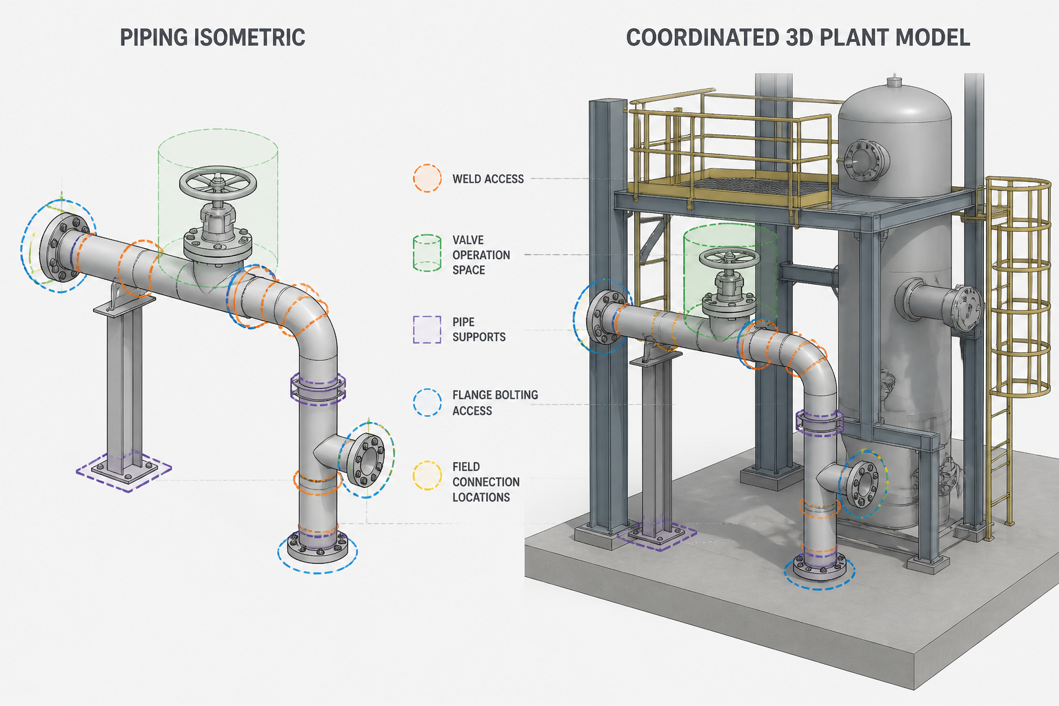
A piping isometric constructability review is a practical check between design completion and field execution. It asks whether the drawing communicates enough reliable information for fabrication, transport, installation, inspection, operation, and maintenance.
This review is broader than checking connectivity or confirming that a bill of materials exists. It evaluates how the line will be assembled in real conditions, where access may be restricted, and whether the drawing agrees with the surrounding design documents. The checklist below provides a disciplined way to examine those issues in a CAD and project-coordination workflow.
A piping isometric can be geometrically correct and still be difficult to fabricate, install, inspect, or maintain. A constructability review examines whether the information shown on the drawing supports real work in the field. It connects design intent with fabrication sequence, lifting access, welding, bolting, support installation, inspection, and future maintenance.
This review is different from checking only pipe connectivity or extracting a bill of materials. Those checks confirm that components and records are present. A constructability review asks whether a crew can understand the intended assembly and carry it out without avoidable rework or unsafe assumptions.
What a constructability review should confirm
The reviewer should be able to answer four basic questions:
- Can the piping be fabricated from the information shown?
- Can the assembled spool or field section be transported and installed?
- Can welds, flanges, valves, supports, and specialty items be reached?
- Are the drawing assumptions clear enough to prevent conflicting field interpretations?
The answer depends on the project’s approved piping specification, modeling requirements, fabrication practice, inspection plan, and construction sequence. The isometric is not a substitute for those documents. Instead, it should communicate their relevant requirements in a coordinated, traceable form.
Start with the drawing and model context
Before inspecting individual components, confirm that the isometric belongs to the correct line, area, revision, and design package. Compare the drawing with the current model, line list, P&ID, support information, and material documentation available for the project.
Check the following items first:
- Line number, service description, and piping specification are consistent.
- Flow direction and connection points agree with the process documentation.
- Revision status and clouded changes are understandable.
- Referenced drawings, support identifiers, and continuation references are present.
- Insulation, tracing, painting, heat treatment, or special fabrication notes are identified where applicable.
A mismatch at this stage can make later geometry checks misleading. For example, a correctly drawn valve may still be the wrong component if the isometric was generated from an outdated specification or an obsolete line record.
Review the physical installation sequence
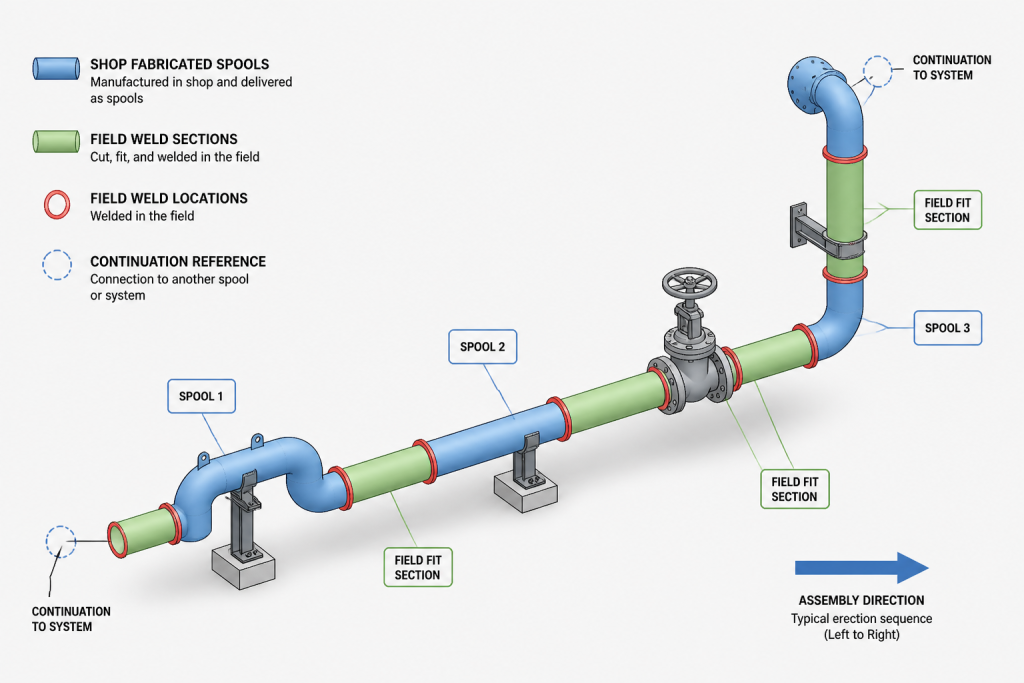
Trace the line in the order that it would likely be assembled. Do not review only from the page’s lower-left corner to its upper-right corner. Follow the actual routing from a known connection, such as equipment, a header, or a battery limit, and consider where prefabricated spools end and field assembly begins.
Look for locations where installation could be blocked by surrounding equipment, structural steel, existing piping, walls, platforms, or temporary construction access. A small gap on an isometric does not prove that physical clearance exists. Use the coordinated model, plan views, elevations, and sections to verify spatial conditions.
| Review area | Constructability question |
|---|---|
| Routing | Can the line be installed without conflicting with nearby systems or required access routes? |
| Assembly | Can each spool or field section be positioned and connected in a practical sequence? |
| Movement | Can components be lifted, rotated, aligned, and supported during installation? |
| Connections | Can welds and flange bolts be reached with the intended tools and procedures? |
| Maintenance | Can operators and maintenance personnel reach valves, instruments, drains, and removable items? |
Check weld and field-joint locations
Weld locations affect both fabrication and installation. Review whether the shown joints divide the line into practical shop-fabricated spools and field sections. A field weld placed in a congested area may be difficult to fit, inspect, coat, or repair. Conversely, too many shop joints can create unnecessary handling and alignment work.
Check that weld identifiers, joint types, and field-weld indicators are used consistently with the project drafting convention. Confirm that the drawing distinguishes field welds from shop welds when that distinction affects planning. Review branch connections, socket or threaded items, flange welds, and specialty components rather than focusing only on the long straight runs.
Do not assume that a visually convenient joint is acceptable. The final location may depend on welding access, nondestructive examination, heat treatment, coating, transportation limits, and the approved fabrication procedure.
Examine valves, flanges, and removable components
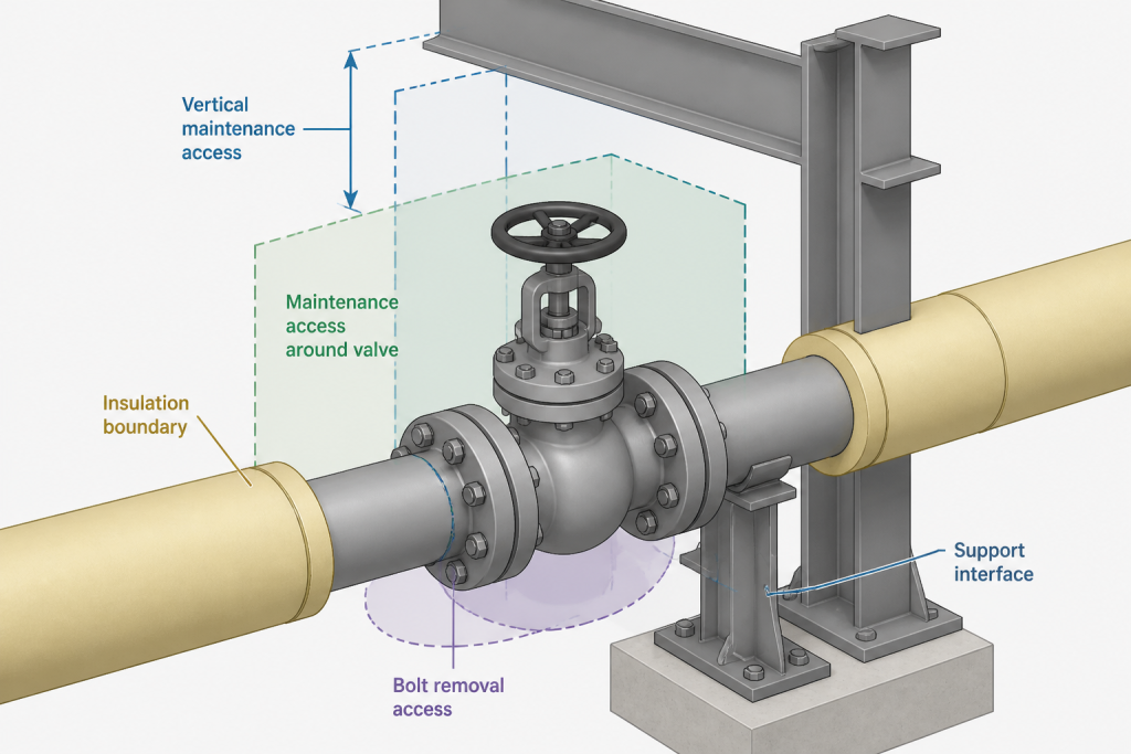
Valves and flanged connections deserve a dedicated pass because they combine orientation, operation, bolting, weight, and maintenance concerns. Confirm that the valve handwheel, actuator, gearbox, or control attachment is oriented as intended and does not interfere with nearby steel or equipment.
For each accessible valve or flange, consider:
- Can the operator reach and operate the valve without standing in an unsuitable location?
- Is there enough surrounding space to remove bolts, spread the flanges, and replace the gasket?
- Can the valve or inline item be removed without dismantling an excessive length of piping?
- Does the orientation agree with the flow direction and equipment connection requirements?
- Are removable covers, strainers, spectacle devices, or specialty items shown with adequate working space?
Use the applicable component reference data for dimensions and facing details. The isometric should identify the selected item correctly, but the drawing itself should not be treated as the sole source for every installation or maintenance requirement.
Review support interfaces and temporary conditions
A support mark on an isometric is only useful when it can be connected to the coordinated support design. Check that support identifiers are complete and that the line can physically meet the support arrangement shown in the model or support detail.
Look for practical interfaces such as shoes, guides, anchors, hangers, clamps, and support attachments. Ask whether insulation, external coating, heat tracing, or a corrosion-protection system changes the interface. Also consider installation conditions: a pipe may need temporary support or restraint before all permanent steel is complete.
This review does not replace stress analysis or support engineering. It verifies that the drafting output does not hide a support conflict, omit an identified support, or place a connection where installation access is unreasonable.
Verify dimensions and field references
Dimensions should allow the fabricator and installer to locate connections and build the line without relying on scaled measurements. Check that dimensions reference stable points and that chained dimensions do not create ambiguity or an unexplained accumulation of tolerances.
Review the relationship between:
- Overall coordinates and local spool dimensions.
- Equipment nozzle locations and piping connection points.
- Branch locations and nearby welds or supports.
- Elevation information and the project’s stated reference system.
- Continuation references and the corresponding drawing numbers or line segments.
When dimensions appear to conflict, do not silently correct the drawing. Mark the issue for resolution and identify the source that should govern. A clear review comment is more valuable than an undocumented adjustment.
Check materials, notes, and identification
Constructability depends on more than geometry. Verify that component tags, material descriptions, ratings, end connections, and special notes agree with the approved piping material information. Pay particular attention to reducers, branch fittings, valves, flanges, gaskets, bolting, specialty items, and small-bore connections.
Also check whether the drawing identifies requirements that affect fabrication or installation, such as cleanliness, preservation, temporary items, inspection hold points, orientation marks, or dimensional control notes. Project procedures govern how these requirements are documented; the review should confirm that required information is not lost between the model and the issued drawing.
A repeatable CAD review workflow
- Confirm the source: Open the current drawing, model view, line data, and revision record.
- Trace the route: Follow the line between connection points and identify every branch, valve, support, and continuation.
- Review the assembly: Divide the route into likely shop spools and field sections.
- Check access: Inspect valve operation, flange bolting, weld access, lifting paths, and maintenance removal space.
- Check interfaces: Compare supports, equipment nozzles, structures, insulation, and adjacent systems.
- Check documentation: Verify identifiers, dimensions, notes, materials, weld marks, and references.
- Record issues clearly: State the location, condition, consequence, and required follow-up for each comment.
- Close the loop: Recheck the updated CAD file and confirm that resolved comments did not introduce new conflicts.
Common review mistakes
One frequent mistake is reviewing the isometric in isolation. A drawing can look complete while hiding a conflict visible only in a plan, section, or coordinated model. Another is checking component identity without checking access. A correctly selected valve is still a constructability concern if its actuator cannot be operated or removed.
Reviewers should also avoid treating every field weld, support, or dimension as a drafting preference. Some decisions are controlled by engineering analysis, fabrication procedures, inspection requirements, or construction planning. Record the uncertainty and route it to the responsible discipline instead of inventing a local rule.
Final perspective
A strong piping isometric constructability review turns a component drawing into a workable installation record. It combines route tracing, assembly planning, access checks, support coordination, dimensional verification, and document control. The most useful review comments are specific, visible in the CAD environment, and tied to an action that another discipline can verify.
Use the isometric as the central communication tool, but compare it with the approved model, specifications, process documents, support details, and construction requirements. That combination helps identify practical problems before fabrication or field installation begins.
How to use this constructability checklist
Review the isometric as part of a document set rather than as an isolated drawing. The model, P&ID, line information, piping specification, support details, equipment data, inspection requirements, and construction plan each answer different questions. The isometric should present their relevant information consistently and make unresolved assumptions visible.
What makes a review comment useful?
A useful comment identifies a precise location, describes the observed condition, explains the likely fabrication or installation consequence, and states what follow-up is needed. This approach helps the responsible discipline resolve the issue without relying on an undocumented CAD adjustment.
- Location: Identify the line segment, connection, component, support, weld, or drawing reference.
- Condition: Describe the access limitation, document mismatch, unclear dimension, missing reference, or coordination concern.
- Consequence: Explain how the issue could affect fabrication, lifting, bolting, inspection, operation, maintenance, or sequencing.
- Action: Direct the issue to the appropriate design, stress, materials, inspection, fabrication, or construction owner.
Why model coordination matters
Isometric graphics simplify three-dimensional routing. They can show the intended relationship between components without proving that a crew can physically reach every joint or move every removable item. Plan views, elevations, sections, and the coordinated model are therefore essential when reviewing congestion, access paths, lifting, support interfaces, and equipment connections.
Constructability is not design substitution
A constructability review does not replace stress analysis, piping material control, welding procedures, inspection planning, lifting studies, or approved construction methods. Its role is to expose conflicts and missing information early, then route those findings to the documents and disciplines that govern the decision.
Frequently Asked Questions
What is a piping isometric constructability review?
It is a structured review of whether a piping isometric supports practical fabrication, transport, installation, inspection, operation, and maintenance. It considers geometry together with access, sequencing, supports, documentation, and surrounding systems.
How is constructability different from piping connectivity checking?
Connectivity checking confirms that components and connections form the intended line. Constructability checking goes further by asking whether the line can be fabricated, assembled, accessed, supported, inspected, and maintained without avoidable field problems.
Should the isometric be reviewed without opening the model?
No. The isometric should be the central communication document, but the coordinated model and related views are needed to verify physical clearance, congestion, installation access, support interfaces, and removal paths.
What should be checked around valves and flanges?
Check orientation, operator access, bolt removal space, gasket replacement access, lifting or handling needs, and the ability to remove the component without unnecessary dismantling. Confirm the component against the approved material and project information.
Who resolves a constructability issue?
The responsible owner depends on the issue. Routing and access concerns may require piping or layout coordination; support concerns may involve stress or support engineering; weld and inspection concerns may require fabrication or quality review. Record the issue clearly rather than applying an unapproved local correction.
What makes an isometric ready for constructability review?
The drawing should have an identifiable line, current revision, coordinated connection points, relevant references, component information, dimensions, support identifiers, weld indications, and applicable fabrication or installation notes. Missing source information should be recorded as a review finding.