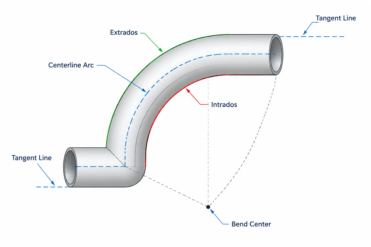
Correctly modeling a pipe bend requires more than drawing an arc between two straight runs. The CAD definition must distinguish the centerline path from the physical pipe envelope, identify where curvature begins and ends, and clarify what any reported length represents.
This guide explains the geometry and terminology used to define pipe bend radius in CAD. It is intended to help piping designers, drafters, engineers, and fabricators review bend models without confusing nominal routing geometry with verified manufacturing data.
A pipe bend is more than a curved solid connecting two straight runs. Its geometry includes a centerline radius, bend angle, tangent points, inside and outside surfaces, and often straight end sections. These features affect routing, clearance checks, drawing dimensions, and fabrication data.
Confusion often begins when a drawing simply lists a “bend radius” without identifying where that radius is measured. In most piping layout work, the controlling value is the centerline radius, but inside radius, outside radius, fitting takeoff, and manufacturer geometry are not interchangeable with it. A reliable CAD model must use the same dimensional basis as the selected component or fabrication method.
What pipe bend radius normally means
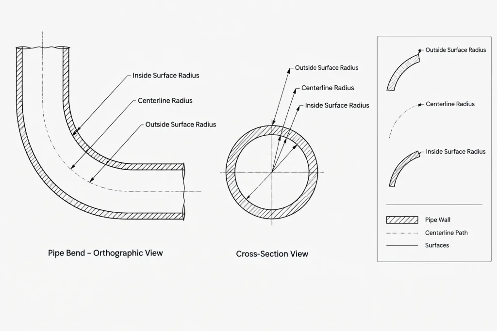
The radius of a piping bend is commonly measured from the bend center to the pipe centerline. This is the centerline radius, often abbreviated CLR. It defines the path followed by the theoretical centerline through the curved portion.
The centerline radius does not describe the pipe bore or either visible edge of the bend. Those surfaces are offset from the centerline by approximately half the actual pipe outside diameter for an ideal circular section.
For basic geometric modeling:
- Centerline radius: Radius from the bend center to the pipe centerline.
- Inside surface radius: Approximately the centerline radius minus one-half of the pipe outside diameter.
- Outside surface radius: Approximately the centerline radius plus one-half of the pipe outside diameter.
If R is the centerline radius and D is the verified outside diameter, the idealized surface radii are:
Inside radius = R − D/2
Outside radius = R + D/2
These relationships are useful for CAD envelopes, but they do not account for bending distortion, wall thinning, flattening, or manufacturing tolerances.
Intrados and extrados terminology
The curved surfaces of a bend have specific names that are useful in fabrication, inspection, and stress discussions.
- Intrados: The inside curve, closest to the center of curvature.
- Extrados: The outside curve, farthest from the center of curvature.
- Crown: The side region between the intrados and extrados.
During bending, the extrados tends to experience stretching while the intrados tends to experience compression. The resulting component may not retain the perfectly circular section shown by a simple swept CAD solid. The extent of wall change and ovality depends on the material, starting wall, bend process, tooling, radius, and fabrication controls.
A general arrangement model usually represents the nominal envelope rather than these localized manufacturing effects. Where minimum wall, bore condition, inspection, or flow performance matters, those issues require engineering and fabrication review beyond the nominal CAD shape.
Bend angle and tangent points
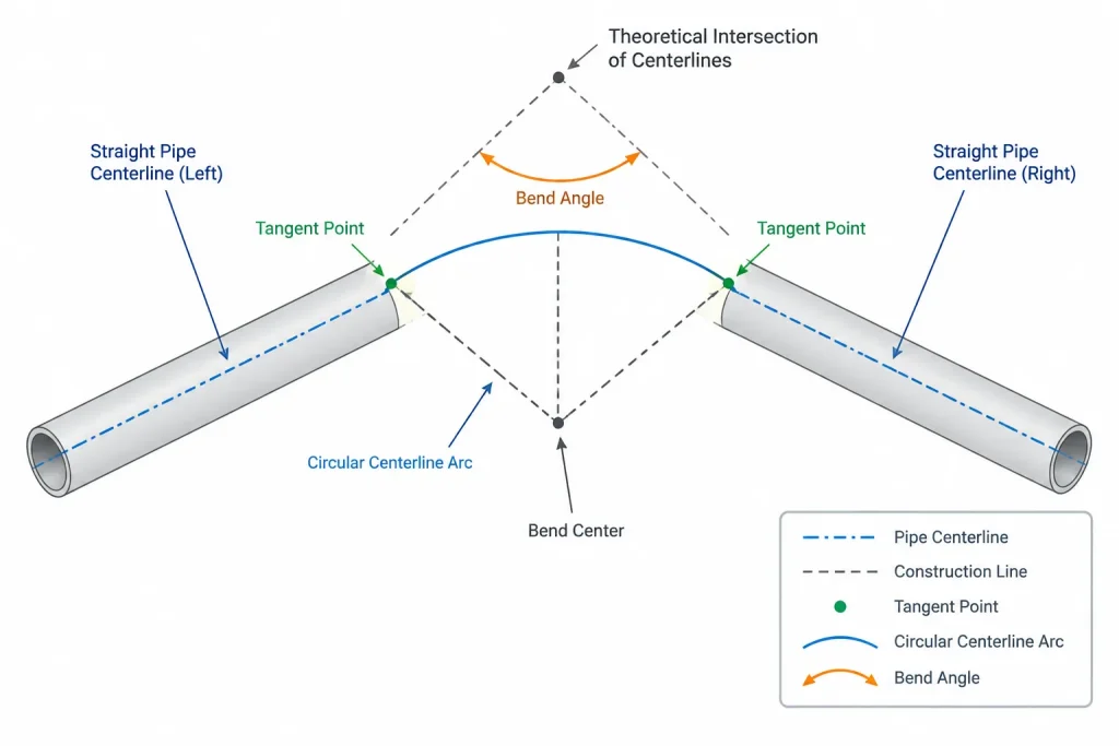
The bend angle is the change in direction between the incoming and outgoing straight centerlines. The curved portion begins and ends at tangent points, where the straight centerline meets the circular centerline arc without an abrupt change in direction.
These tangent points are important because they separate three different pieces of geometry:
- The straight inlet tangent
- The circular bend arc
- The straight outlet tangent
Dimensions placed to a tangent point control the start or end of curvature. Dimensions placed to the theoretical intersection of the two straight centerlines control a different point. For many bend configurations, that theoretical intersection lies away from the physical pipe centerline arc.
CAD users should not substitute the apparent corner of extended centerlines for a tangent point unless the drawing convention clearly defines that basis. A fabrication drawing should identify whether a dimension controls the tangent, end plane, centerline intersection, weld end, or another datum.
Centerline arc length and developed length
For an ideal circular bend, the theoretical centerline arc length can be calculated from the centerline radius and bend angle:
Centerline arc length = R × θ
In this expression, R is the centerline radius and θ is the bend angle expressed in radians. The same relationship may be written with an appropriate angular conversion when the drawing uses degrees.
This result is a geometric arc length, not automatically a fabrication cut length. A real bent-pipe blank may also include straight tangents, grip lengths, end preparation, trim allowance, calibration allowance, and process-specific compensation. Material movement during bending can also affect how the fabricator establishes the starting blank.
For that reason, CAD-derived developed length should be labeled according to what it actually represents. Useful distinctions include:
- Theoretical centerline arc length: Length along the ideal curved centerline only.
- Centerline developed length: Arc plus any defined straight centerline portions.
- Nominal blank length: Starting length before process allowances, if established by the fabrication method.
- Cut length: Controlled shop value including the applicable end and process allowances.
A designer should not present a theoretical sweep length as a shop-ready cut length unless the fabrication workflow has validated that use.
Bends, elbows, and radius designations
A fabricated or induction bend and a manufactured elbow may create a similar change in direction, but their dimensional definitions can differ. An elbow is generally selected as a standardized fitting with established center-to-end geometry. A bend may be defined by its centerline radius, angle, tangent lengths, and fabrication method.
Do not infer the radius of an elbow solely from a generic visual shape, and do not replace a specified bend with an elbow just because both connect the same route centerlines. The substitution can change:
- End locations and pipe cut lengths
- Weld locations
- Clearance around the outside arc
- Pressure-drop assumptions
- Stress flexibility
- Material takeoff and fabrication method
Likewise, descriptions such as “multiple-diameter bend” can be ambiguous unless the project states what diameter basis is used. Nominal pipe size is not the same as actual outside diameter. The CAD record should preserve the specified terminology rather than silently converting the description using an assumed diameter.
Which dimensions control the CAD model?
| Input | What it controls | Common risk |
|---|---|---|
| Centerline radius | Curved path of the pipe centerline | Using an inside or outside radius instead |
| Actual outside diameter | Physical outer envelope | Using nominal size as a geometric diameter |
| Wall thickness | Nominal bore representation | Assuming the modeled bore represents minimum post-bend wall |
| Bend angle | Change in route direction | Confusing bend angle with drawing orientation |
| Tangent lengths | Straight portions adjoining the arc | Omitting required straight ends or grip zones |
| End planes | Connection and cut-length limits | Dimensioning only to tangent points |
The correct controlling set depends on whether the model represents a catalog fitting, a custom shop bend, an induction bend, or a field-routed item. Where manufacturer or fabricator data is available, that verified geometry should take precedence over a generic bend primitive.
A practical CAD modeling workflow
1. Confirm the dimensional basis
Identify the pipe size, actual outside diameter, selected wall, centerline radius, bend angle, end type, and required straight tangents. Do not derive actual diameter from a nominal-size label without consulting verified dimensional data.
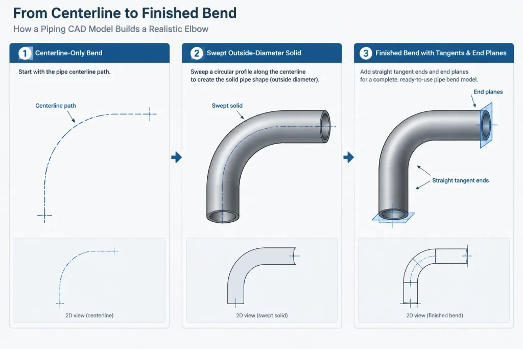
2. Build the centerline first
Create the incoming and outgoing route centerlines, locate their theoretical intersection, and construct the specified tangent arc. Confirm that the arc is tangent to both straight segments.
3. Generate the physical envelope
Sweep the correct outside profile along the centerline. If the model includes a bore, use the nominal dimensions appropriate to the selected pipe, while recognizing that a perfect concentric bore does not simulate bending deformation.
4. Add controlled end geometry
Place end planes, weld ends, flange faces, or other connections from the specified datums. Keep end-to-end dimensions separate from the curved arc length.
5. Check surrounding clearance
Review the extrados against structure, equipment, adjacent piping, insulation, and access zones. A centerline-only check can miss interference at the outside of the curve.
6. Document assumptions
If the bend is preliminary, identify the assumed radius and tangent basis in component data or drawing notes. Replace assumptions when procurement or fabrication information becomes available.
Drawing and data-control recommendations
A useful bend definition should communicate more than an angle. Depending on project practice, the controlled information may include centerline radius, bend angle, tangent-to-end dimensions, end connections, orientation, material specification, and fabrication notes.
Avoid over-dimensioning the same geometry from multiple datums. For example, controlling the radius, tangent points, theoretical intersection, and both end locations independently can create a closed dimension loop. Select a clear dimensional hierarchy and treat other values as reference or derived information where appropriate.
Finally, distinguish nominal CAD geometry from acceptance criteria. A model can define routing space and connection points, but it does not by itself verify wall thinning, ovality, surface condition, heat treatment, dimensional tolerance, or suitability for service. Those items must be checked against the governing design documents, purchase requirements, and verified fabrication data.
How to review a pipe bend model
A bend model should be checked from the route centerline outward. Begin by confirming the radius basis and bend angle, then verify the tangent points, straight end portions, connection planes, and physical envelope. This sequence helps prevent an inside or outside surface radius from being mistaken for the controlling centerline radius.
Geometry checks
- Radius basis: Confirm whether the stated radius applies to the centerline, intrados, extrados, or another defined surface.
- Pipe envelope: Use verified outside-diameter data rather than treating nominal pipe size as a physical diameter.
- Tangency: Check that the curved centerline joins each straight centerline smoothly at the intended tangent point.
- End definition: Distinguish tangent locations from weld ends, cut planes, flange faces, and other connection datums.
- Clearance: Review the complete outside envelope, including any insulation or project-defined access space, rather than checking the centerline alone.
Length checks
Any length extracted from CAD should be named according to its basis. The length of the curved centerline is not necessarily the total developed centerline, starting blank, or controlled shop cut length. Straight ends, trimming, end preparation, tooling needs, and fabrication allowances may be handled separately by the applicable workflow.
Model maturity and data ownership
A preliminary routing bend may be adequate for layout coordination while still lacking fabrication-controlled geometry. As component, supplier, or fabricator information becomes available, the model should be reviewed against that verified data. Assumed values should remain identifiable so they are not mistaken for approved production information.
The final drawing or model record should also make clear which dimensions control and which are derived. This reduces closed dimension loops and gives downstream users a consistent basis for checking routing, takeoff, fabrication, and installation interfaces.
Frequently asked questions
Is pipe bend radius measured to the inside surface?
Not normally when centerline radius is specified. The drawing or component definition should explicitly identify the measurement basis because the centerline, intrados, and extrados have different radii.
What is the difference between the intrados and extrados?
The intrados is the inside curve nearest the center of curvature. The extrados is the outside curve farthest from that center. These terms are useful when discussing bend clearance, deformation, wall condition, and inspection.
Is centerline arc length the same as pipe cut length?
No. Centerline arc length describes the ideal curved path only. A cut length may also account for straight portions, end preparation, trimming, fabrication allowances, and process-specific requirements.
Why can a centerline-only CAD check miss a clash?
The extrados extends beyond the route centerline and defines the outer side of the bend envelope. Adjacent piping, structure, equipment, insulation, and access requirements therefore need to be checked against the physical model or an appropriate clearance envelope.
Can a standard elbow be substituted for a fabricated bend?
Not solely because the route changes direction by the same angle. The alternatives may have different end locations, weld positions, clearance envelopes, flexibility, takeoff, and fabrication requirements. Any substitution must be checked against the governing design and component data.
Does a swept CAD solid represent post-bend wall condition?
A simple sweep normally represents idealized nominal geometry. It does not by itself establish actual wall thinning, ovality, bore condition, surface condition, or fabrication tolerance.