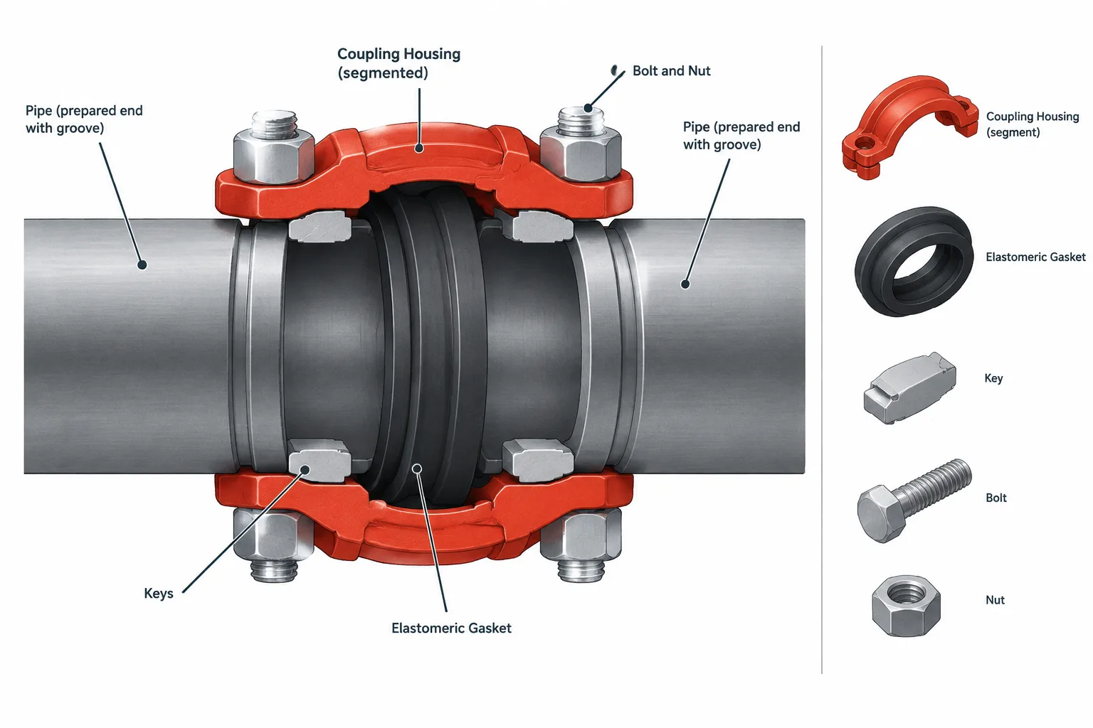
Grooved pipe joints in piping CAD require more than a recognizable coupling shape. The model must distinguish the external housing from the prepared pipe ends, gasket interface, connection planes, and any verified movement behavior.
This guide explains how those features affect component selection, pipe cut-length references, clearance checks, fabrication documentation, and model handoff. It also clarifies why roll grooves, cut grooves, rigid couplings, and flexible couplings should not be treated as interchangeable CAD geometry.
Grooved pipe joints are often recognizable in a model by the coupling housing wrapped around two prepared pipe ends. That simple exterior shape can hide several important design details: the pipe-end groove, the internal gasket, the relationship between the pipe ends, and the coupling’s ability—or inability—to accommodate movement.
For piping designers and drafters, a grooved connection should not be treated as a generic clamp placed over an ordinary butt joint. Its geometry and behavior depend on the selected coupling system, pipe material, wall, groove preparation, and product configuration. A useful CAD model must represent the interfaces needed for layout, fabrication, purchasing, and coordination without implying unverified performance.
What Makes a Pipe Joint “Grooved”?
A grooved joint uses circumferential grooves near the ends of the joined components. Coupling housing segments engage those grooves, while an elastomeric gasket provides the pressure seal. Bolts and nuts draw the housing segments together according to the coupling design.
The primary parts of a typical joint are:
- Two grooved pipe ends, fitting ends, valve ends, or equipment connections
- An elastomeric gasket positioned around the adjoining ends
- Housing segments with keys that engage the grooves
- Bolts and nuts that assemble the housing
The housing is visible externally, but the groove and gasket are functionally essential. A simplified model may omit their detailed profiles, yet the component record should still identify the correct end preparation and coupling type.
Roll Grooves and Cut Grooves Are Not the Same Geometry
Grooves may be formed by rolling or cutting, depending on the pipe and the permitted preparation method. The two processes should not be represented or specified interchangeably.
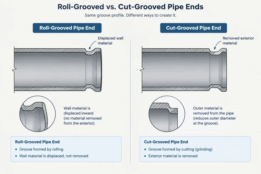
Roll-grooved pipe
Roll grooving forms the groove by displacing the pipe wall rather than machining material away. This operation changes the local pipe-end profile and generally creates an inward projection into the bore near the groove. The resulting internal geometry can matter where bore smoothness, cleaning, drainage, lining, or flow characteristics are important.
Cut-grooved pipe
Cut grooving removes material from the outside surface to create the groove. Because material is removed, the remaining wall beneath the groove must be evaluated for the selected pipe and service. A CAD note should not authorize cut grooving merely because a groove can be drawn on the model.
The allowed preparation is a specification and product-selection issue. Designers should verify compatibility among pipe material, actual wall, groove dimensions, coupling design, fabrication method, and service requirements. Nominal pipe size or schedule alone does not establish that compatibility.
Rigid and Flexible Couplings
Grooved couplings are commonly described as rigid or flexible, but those terms refer to product behavior rather than just visual appearance.
| Coupling description | General behavior | CAD concern |
|---|---|---|
| Rigid | Intended to restrain relative angular and axial movement at the joint within the product’s defined behavior | Do not model the connection as a hinge or expansion device |
| Flexible | May permit controlled angular deflection, axial movement, or both when installed within verified limits | Show the installed geometry and separately document any permitted movement envelope |
A flexible coupling is not automatically a substitute for an engineered expansion joint, piping loop, or other movement strategy. Available movement depends on the actual coupling, pipe ends, installation condition, system arrangement, and manufacturer instructions. Movement assigned to one joint may also affect supports, branches, equipment nozzles, and neighboring joints.
Likewise, the word rigid should not be interpreted as meaning that the joint or connected piping has infinite stiffness. Stress analysis and support decisions require appropriate engineering data rather than assumptions based on the catalog description.
Pipe-End Gap and Engagement
The relationship between the two pipe ends is a controlled joint condition. Depending on the system, the ends may have a specified separation, permitted range, or installation position. The coupling housing and gasket bridge the interface, while the housing keys engage the prepared grooves.

Several CAD errors can result from treating the coupling as a simple sleeve:
- Placing pipe ends at the coupling’s exterior center without checking the required end condition
- Assuming the ends must touch
- Using an arbitrary visible gap as a fabrication dimension
- Measuring pipe cut length to the outside edge of the housing
- Ignoring axial positions needed for installation or movement
Pipe cut length should be controlled from meaningful fabrication references, usually prepared pipe ends and established component connection points. The outer edges of a coupling housing are generally poor cut-length datums because they describe the assembled envelope rather than the pipe-end preparation.
How Much Detail Should the CAD Model Include?
The appropriate model detail depends on what the model must support. A coordination model may only need an accurate external envelope and connection locations. A fabrication model may also need groove callouts, pipe-end references, assembly data, and verified product geometry.
Useful elements for a simplified model
- Correct nominal connection size
- Verified coupling width and outside envelope where clearance matters
- Pipe centerline and connection-axis alignment
- Pipe-end or component-end reference planes
- Coupling classification, such as rigid or flexible
- End-preparation metadata identifying a grooved connection
Details that may be represented symbolically
- Housing segment split lines
- Bolt and nut shapes
- Internal gasket cross-section
- Exact groove profile
- Small casting features and markings
If the model is used to generate fabrication information, symbolic geometry must not be mistaken for tooling dimensions. Groove width, depth, location, tolerances, and pipe-end requirements should come from the governing project documents and verified product data.
Couplings Require Clearance Too
A grooved coupling often projects beyond the pipe outside diameter. The housing, bolt pads, bolts, and nuts can conflict with nearby steel, walls, insulation, cable tray, adjacent piping, or support hardware. A centerline-only layout can miss these clashes.
Designers should consider both the operating envelope and the assembly envelope. Workers may need room to position the gasket, install housing segments, insert or tighten fasteners, and inspect the completed joint. If the joint is intended as a maintenance break, there must also be a realistic method for separating or removing the connected component.
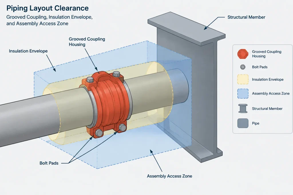
Insulation requires additional coordination. The coupling may need a locally enlarged insulation envelope or a removable cover. The required treatment should be coordinated with the insulation specification rather than inferred from the bare coupling shape.
Fittings, Valves, and Adapters with Grooved Ends
Grooved systems can include elbows, tees, reducers, caps, valves, mechanical branch components, and adapters to other connection types. Their end-to-end or center-to-end dimensions should not be derived by scaling a generic fitting.
A grooved-end valve, for example, needs verified body geometry, connection locations, operator orientation, and maintenance clearances. An adapter may introduce a grooved end on one side and a flanged, threaded, welded, or otherwise prepared end on the other. Each end should have its own connection definition in the CAD component record.
Reducers also require attention to the actual product arrangement. A reducing coupling and a separate grooved reducer are not necessarily equivalent in length, bore transition, flexibility, or purchasing identity. They should remain distinct catalog items.
A Practical CAD Workflow
- Identify the piping specification. Confirm whether grooved construction is permitted for the service, material, size range, and connection location.
- Select the connection concept. Determine whether the joint needs a rigid coupling, flexible coupling, reducing coupling, adapter, or another specific component.
- Verify product geometry. Obtain controlled dimensions for the housing envelope, component length, connection points, and other layout-critical features.
- Define pipe-end references. Place connection planes where the prepared pipe ends actually occur, not at an arbitrary housing midpoint.
- Assign metadata. Record coupling type, end preparation, material description, gasket requirement, and catalog identifier as required by the project.
- Check clearance. Review the housing, fasteners, insulation, assembly access, and maintenance path against nearby objects.
- Control fabrication output. Keep pipe cut lengths, groove preparation instructions, and installation requirements tied to verified documents.
- Review movement assumptions. If flexibility is used intentionally, coordinate the permitted movement with piping analysis, supports, equipment interfaces, and installation position.
Common Modeling and Documentation Mistakes
- Using one generic coupling block for every manufacturer or coupling type
- Scaling a coupling model to represent another pipe size
- Labeling a joint flexible without documenting what movement is intended
- Showing grooved ends while the bill of materials lists plain-end components
- Failing to distinguish roll-grooved and cut-grooved preparation
- Dimensioning pipe from the outside of the coupling housing
- Omitting bolt-pad and insulation clearance
- Assuming a grooved valve has the same laying length as another end-connection version
What the Model Should Communicate
A reliable grooved-joint model does more than show a recognizable coupling. It communicates where the component connects, what pipe-end preparation is required, how much space the assembly occupies, and whether any movement characteristic is being used by design.
Generic geometry is useful during early layout, but it should carry a clear status until the dimensions and product selection are verified. Replacing placeholders with controlled catalog components prevents a visually convincing model from becoming an unintended fabrication instruction.
Model Geometry and Component Data Should Agree
A grooved coupling can look correct while carrying incomplete or conflicting data. The graphical component, connection definition, piping specification, and material record should describe the same joint concept. If the model shows grooved ends but the component data describes plain ends or another connection type, downstream drawings and material reports may become unreliable.
It is useful to separate information into two groups:
- Geometric information: external envelope, connection axis, prepared-end reference planes, fastener projection, operator orientation, and access space.
- Specification information: coupling classification, groove preparation, gasket requirement, pipe compatibility, component identity, and verification status.
This separation allows a coordination model to remain visually efficient while retaining the information needed for later product selection and fabrication review.
Use Clear Placeholder Status
Generic coupling geometry can support early routing and clash detection, but it should be identified as preliminary when product dimensions and joint conditions have not been confirmed. A placeholder should not silently become the source for pipe cut lengths, groove preparation, movement allowances, or purchasing descriptions.
Before model release, review whether each grooved component has verified connection locations, an appropriate external envelope, consistent end-preparation data, and adequate installation access. Any intended flexibility should also be documented as an engineering requirement rather than inferred from the appearance of the coupling.
Grooved-Joint Model Review Questions
- Does the component record identify the joint as grooved?
- Are pipe-end reference planes separate from the outside edges of the housing?
- Is the groove preparation consistent with the pipe and selected coupling system?
- Does the model distinguish rigid, flexible, reducing, and transition components?
- Are housing, fastener, insulation, assembly, and maintenance clearances represented or documented?
- Is any movement assumption supported by verified product and engineering information?
- Are fabrication details controlled by approved documents rather than symbolic CAD geometry?
Frequently Asked Questions
Should the gasket be modeled in a grooved pipe joint?
Not always. A simplified coordination model may represent the gasket through component metadata rather than detailed geometry. A section view, installation illustration, or fabrication-oriented model may require a clearer symbolic representation. The CAD geometry should not be used to infer an unverified gasket profile.
Can the coupling housing midpoint be used as the pipe connection point?
Not by assumption. Connection planes should represent the actual prepared pipe ends or established component connection references. The housing midpoint describes the coupling envelope and may not define either pipe-end location.
Does a flexible coupling eliminate the need for movement analysis?
No. Flexible describes product behavior under defined conditions. Any intended angular or axial movement must be coordinated with supports, branches, equipment interfaces, neighboring joints, and the verified installation condition.
Can the same groove geometry represent roll-grooved and cut-grooved pipe?
A symbolic model may use simplified graphics, but the two preparations should remain distinct in specifications and component data. Their formation methods and resulting pipe-end conditions are different.
Is a generic coupling model acceptable for clash detection?
It can be useful during preliminary layout if its status is clear and its envelope is appropriate for the intended check. Product-specific geometry should replace or validate the placeholder before it controls fabrication, purchasing, access planning, or final coordination.