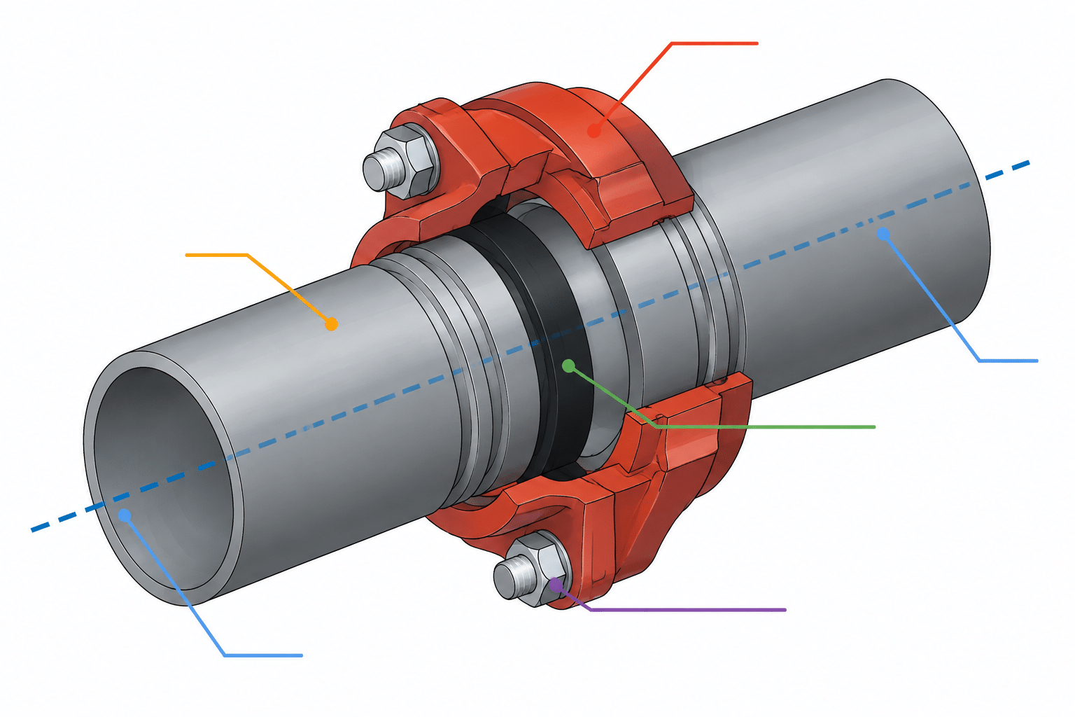
Grooved pipe connections in CAD require more control than their simple external shape suggests. The visible housing is only one part of an assembly whose connection references, pipe-end conditions, fitting takeouts, and product identity can affect routing, fabrication, coordination, and material reporting.
This guide explains how to represent grooved couplings and fittings without confusing the coupling envelope with the pipe cut length. It also highlights the modeling differences between rigid and flexible products, the importance of meaningful connection ports, and the need to verify product-specific geometry before using a component for fabrication or clearance decisions.
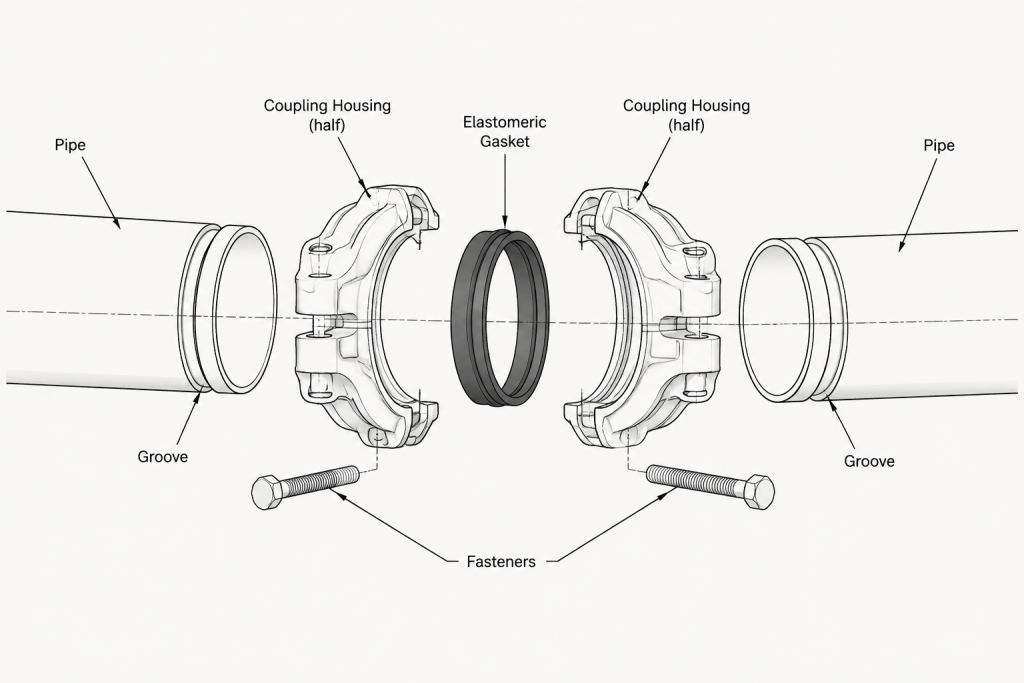
Grooved pipe connections can look simple in a piping model: two pipe ends meet inside a coupling, and the coupling housing covers the joint. In fabrication and installation, however, the assembly depends on several separate features—the pipe-end grooves, gasket, coupling keys, housing segments, bolts, and the intended relationship between the pipe ends.
A useful CAD representation must do more than resemble the outside of a coupling. It should preserve the dimensions and data needed to locate fittings, calculate pipe cut lengths, prepare a bill of materials, and distinguish between rigid and flexible joint behavior. Because grooved systems are commonly based on manufacturer-specific product geometry, designers should verify dimensions from the selected product data rather than scaling a generic block or assuming that similar-looking components are interchangeable.
What makes a grooved connection different?
A grooved connection joins prepared pipe ends using a gasket and an external mechanical coupling. Each pipe end has a circumferential groove. Keys formed into the coupling housing engage those grooves, while the gasket seals around the pipe ends. Bolts draw the housing segments together according to the coupling design.
The coupling does not work like a threaded connection, where one component is screwed into another, or like a butt-welded joint, where the pipe ends become a continuous welded assembly. Its installed geometry depends on the selected coupling, the groove preparation, the pipe outside diameter, and the manufacturer’s assembly requirements.
The groove itself may be produced by different preparation methods. These methods do not necessarily create identical pipe-end profiles or have the same application limits. CAD notes and material descriptions should therefore identify the required end preparation where that information affects procurement or fabrication.
Rigid and flexible couplings are not the same
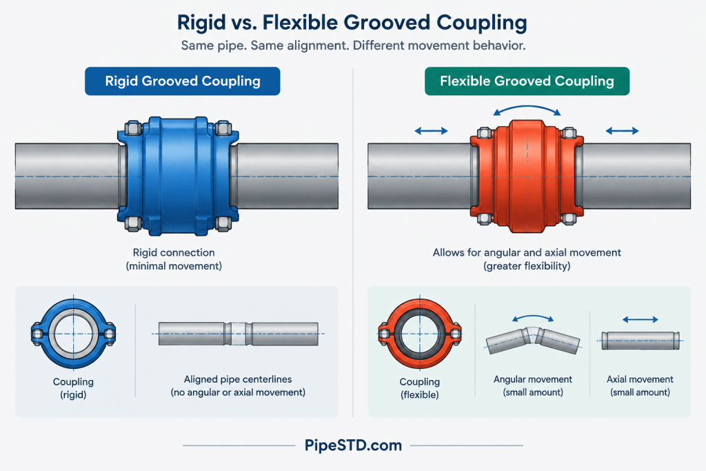
One of the most important modeling distinctions is whether the specified coupling is rigid or flexible. The terms describe intended joint behavior, not simply the appearance of the housing.
| Characteristic | Rigid coupling | Flexible coupling |
|---|---|---|
| General behavior | Intended to restrain relative angular and axial movement within the product’s defined behavior | May permit controlled angular deflection, axial movement, or both within verified limits |
| CAD treatment | Usually modeled as an aligned connection unless product data requires otherwise | May require movement or deflection information outside the basic geometric model |
| Layout assumption | Should not automatically be treated as a welded joint | Should not automatically be treated as an expansion joint |
| Required verification | Product type, dimensions, installation condition, and restraint behavior | Permitted movement, pressure effects, support arrangement, and installation condition |
A flexible coupling’s ability to accommodate some movement does not mean that a piping system can rely on it for unrestricted thermal expansion. System movement, pressure thrust, support reactions, equipment loads, and cumulative joint behavior require engineering review. CAD should communicate the selected component and intended configuration without implying an unverified flexibility function.
The pipe-end gap is a controlled assembly condition
Two pipes inside a grooved coupling should not automatically be modeled as if their ends touch. Depending on the coupling and installation procedure, the assembly may have a defined or permitted relationship between the pipe ends. That relationship can influence cut lengths, fitting locations, and overall spool dimensions.
At the same time, a drafter should not invent a visible gap merely to make the model look realistic. The correct condition must come from verified product data, fabrication practice, and project requirements. A symbolic model may show a joint node without representing the internal gap at all. A fabrication model may need enough detail to control each pipe endpoint.
Three dimensions must be kept separate
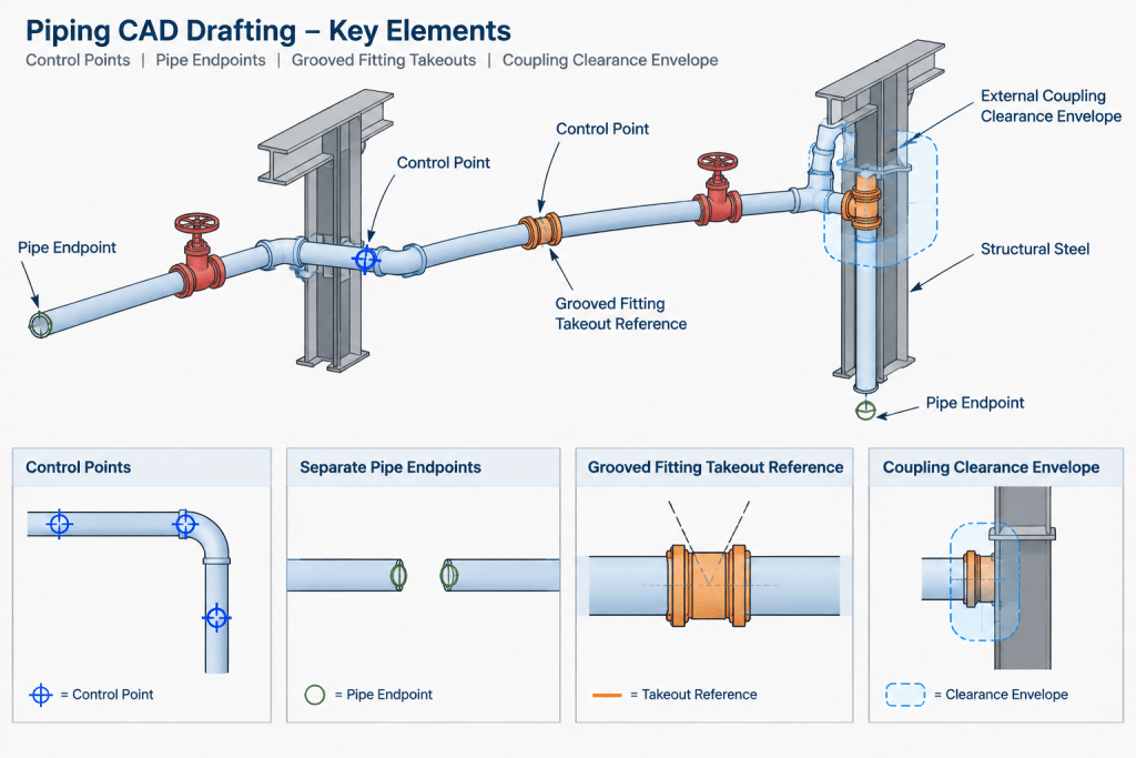
- Pipeline control dimension: The dimension locating the route, fitting center, equipment connection, or other design point.
- Pipe cut length: The physical length of a pipe piece before it is assembled between grooved components.
- Coupling envelope: The external housing width and diameter used for clearance and interference checks.
These values serve different purposes. The coupling envelope does not define the pipe cut length, and the midpoint of the visible housing is not always an appropriate fabrication endpoint. A reliable model uses explicit connection points and verified component dimensions instead of deriving fabrication measurements from graphics.
How grooved fittings affect takeout
Grooved elbows, tees, reducers, caps, and adapters have dimensional takeouts just as welded or flanged fittings do. Their center-to-end, end-to-end, or branch dimensions must come from the selected fitting data. A generic elbow radius or a fitting copied from another connection system may shift the downstream route even when the nominal size appears correct.
Adapters require particular attention because they create an interface between connection types. A grooved-to-flanged adapter, for example, has both a grooved-end reference and a flange-face reference. A grooved-to-threaded adapter introduces a threaded makeup condition. The CAD component should expose ports that correspond to meaningful assembly references rather than placing every insertion point at the visual center of the object.
Reducers should also retain their actual end-size order. A model or bill of materials that identifies only a large size and small size may still be ambiguous if the component orientation is lost. Port data should show which end connects to each line segment.
Choosing the right level of CAD detail
Grooved connections can be represented at several levels of detail. The appropriate choice depends on the drawing purpose.
Schematic or routing representation
For an early layout, the coupling may be a simple symbol or short cylindrical envelope placed at a connection node. This is usually enough to count joints and reserve approximate space, provided that the object carries correct identity and size data.
Coordination representation
A coordination model should show the coupling’s verified external envelope where nearby steel, walls, insulation, equipment, or other services could interfere with it. Bolt pads or housing projections may matter even when the internal gasket and groove details do not.
Fabrication representation
A fabrication-oriented model may need separate pipe endpoints, fitting takeouts, coupling identification, and spool dimensions. Modeling the detailed groove profile is rarely necessary unless it supports a specific manufacturing or inspection task. Excessive groove geometry can increase model complexity without improving the drawing.
The best model is therefore not always the most detailed model. It is the model that preserves the correct interfaces, dimensions, metadata, and clearance envelope for its intended use.
Insulation, clearance, and accessibility
The outside of a grooved coupling is larger than the connected pipe. This enlarged envelope should be considered near structural members, penetrations, adjacent lines, and equipment surfaces. A centerline-only clash check can miss interference between the housing and nearby objects.
Insulation treatment also requires project-specific review. The insulation system may continue over the coupling, stop at the joint, use a removable cover, or require a different local thickness or weatherproofing detail. CAD should not simply extend the pipe insulation cylinder through the coupling unless that representation matches the insulation design.
Installation and maintenance access may require room to assemble the housing segments and operate tools on the fasteners. A coupling that fits geometrically between two objects may still be difficult to install or inspect. These access needs are best reviewed with the construction and maintenance teams instead of being inferred from the coupling body alone.
Recommended component data
A reusable grooved-component library should carry enough information to distinguish visually similar products. Useful fields include:
- Component type and joint function
- Nominal size or end-size combination
- Rigid or flexible designation, where applicable
- Pipe-end preparation requirement
- Compatible pipe outside-diameter basis
- Material and service description required by the piping specification
- Verified fitting takeout or adapter length
- External clearance envelope
- Manufacturer and catalog identifier when the design is product-specific
- Connection-port locations and port types
Do not treat a nominal-size match as proof of compatibility. The coupling, gasket, groove profile, pipe material, outside diameter, service, and installation method must be checked as a complete system.
A practical CAD review workflow
- Confirm the piping specification. Identify the permitted grooved components, materials, gaskets, and end-preparation requirements.
- Select verified product geometry. Use current project-approved data for coupling envelopes and fitting takeouts.
- Establish meaningful ports. Place ports at pipe or component connection references, not arbitrary graphic centers.
- Model each pipe segment independently. Avoid using one continuous pipe object through a joint when fabrication requires separate pieces.
- Apply the intended end condition. Represent or document the pipe-end relationship only from verified assembly information.
- Check downstream dimensions. Confirm that fitting takeouts and adapter lengths do not shift equipment or branch locations.
- Review clearance and access. Include housing projections, insulation treatment, and tool access where relevant.
- Validate the bill of materials. Make sure couplings, fittings, adapters, gaskets, and other required items are counted and described correctly.
- Separate design from installation notes. Do not place unsupported assembly instructions on drawings; reference approved project procedures instead.
Common modeling mistakes
- Using the same generic coupling block for rigid and flexible products
- Assuming all grooved components of the same nominal size are interchangeable
- Making pipe ends touch without checking the intended assembly condition
- Calculating cut lengths from the visible edges of the coupling housing
- Using welded-fitting takeouts for grooved fittings
- Ignoring the housing envelope during clash detection
- Allowing insulation geometry to conceal an inaccessible joint
- Counting the coupling graphically while omitting it from the bill of materials
- Using a flexible coupling as an assumed thermal expansion solution without engineering review
Final drafting principle
A grooved connection should be treated as an assembly and a data-controlled interface, not merely as a sleeve drawn around a pipe joint. Accurate CAD work depends on verified fitting takeouts, meaningful connection ports, explicit pipe segments, correct coupling identification, and realistic clearance envelopes. When those elements are controlled, the model can support layout, coordination, spool development, and material reporting without pretending to replace the selected manufacturer’s installation requirements or the project engineering review.
Model acceptance checks before drawing release
A grooved assembly should pass both a geometric review and a data review. A component can look correct while carrying the wrong connection behavior, end preparation, fitting orientation, or material description. Conversely, a data-rich object may still be unsuitable if its housing envelope or ports do not match the selected product.
Geometry checks
- Confirm that each pipe piece terminates at an intentional connection reference.
- Verify that fitting takeouts and adapter references come from the selected product data.
- Check the complete coupling envelope against nearby piping, structure, equipment, penetrations, and insulation.
- Make sure reducers and adapters retain the correct end orientation.
- Do not infer pipe cut points from the visible edges or midpoint of the housing.
Data checks
- Identify the coupling as rigid or flexible where that distinction applies.
- Record the required pipe-end preparation and compatible outside-diameter basis.
- Preserve manufacturer and catalog identity when geometry or compatibility is product-specific.
- Confirm that couplings, fittings, adapters, gaskets, and related assembly items appear correctly in material reports.
- Keep installation requirements separate from unsupported drafting assumptions.
Managing symbolic and fabrication representations
A practical CAD library may use more than one graphical representation of the same approved component. A lightweight symbol can support routing and joint counting, while a verified envelope can support coordination. A fabrication representation can expose individual pipe endpoints and fitting references without modeling every groove or gasket feature.
These representations should share a controlled component identity. Switching display detail should not change the part description, port locations, end types, or bill-of-materials behavior. This approach limits unnecessary model complexity while preserving the information required by each project phase.
Handoff information for fabrication and field review
Before issuing a grooved piping model, clarify which dimensions are design controls and which must be established from approved product and installation data. Fabricators should be able to distinguish route dimensions, component takeouts, pipe cut lengths, and external clearance envelopes without measuring the CAD graphics.
Any assumed pipe-end relationship should be visible in the model data, spool information, or approved project documentation. If that condition remains unresolved, flag it for verification rather than embedding an unverified gap or contact condition in the fabrication geometry.
Frequently asked questions
Should pipe ends touch inside a grooved coupling model?
Not by default. The intended relationship between the pipe ends depends on verified product data, installation requirements, and project practice. A routing model may omit the internal condition, while a fabrication model may need explicit endpoints.
Can the coupling housing width be used to calculate pipe cut length?
No. The housing is an external clearance envelope, not a substitute for connection references or verified fitting takeouts. Cut lengths should be calculated from controlled pipe endpoints and approved component geometry.
Does a flexible coupling function as an expansion joint?
It should not be assumed to do so. Any permitted movement is product- and installation-dependent, and system behavior also involves supports, pressure effects, equipment loads, and cumulative movement. Engineering review is required.
How much detail should a grooved coupling CAD object contain?
Use the detail needed for the drawing purpose. Routing may require a symbol and reliable metadata, coordination needs a verified external envelope, and fabrication may require separate pipe endpoints and product-specific takeouts. Detailed groove geometry is useful only when it supports a defined task.
Why should rigid and flexible couplings use different CAD identities?
They represent different intended joint behaviors even when their housings appear similar. Separate identities help prevent incorrect specifications, movement assumptions, and material reports.
What information should a grooved fitting port contain?
The port should identify a meaningful connection reference, end type, end size, and orientation. Where compatibility is product-specific, the component data should also preserve the applicable pipe-end preparation and product identity.
Can a generic grooved coupling block be used for clash detection?
Only as a preliminary placeholder. Reliable coordination requires the verified housing envelope and any projections that could conflict with structure, equipment, insulation, or adjacent services.