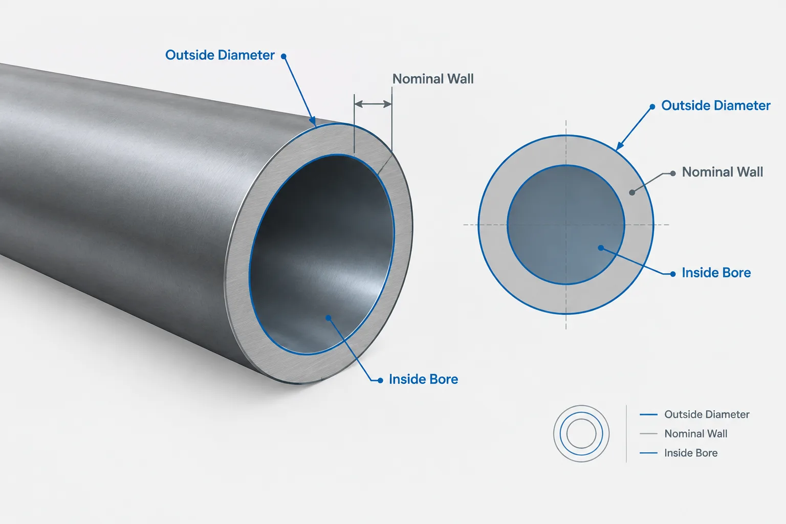
Pipe mill tolerance in CAD is primarily a question of information control: the design calculation, purchasing specification, inspection record, and model may each contain a valid wall thickness with a different meaning. Problems arise when one value is substituted for another without checking its basis.
This guide explains how to distinguish nominal, required, supplied, measured, and modeled wall thickness. It also shows why a standard piping model generally represents nominal geometry while engineering minimums and verified bore requirements remain controlled data.
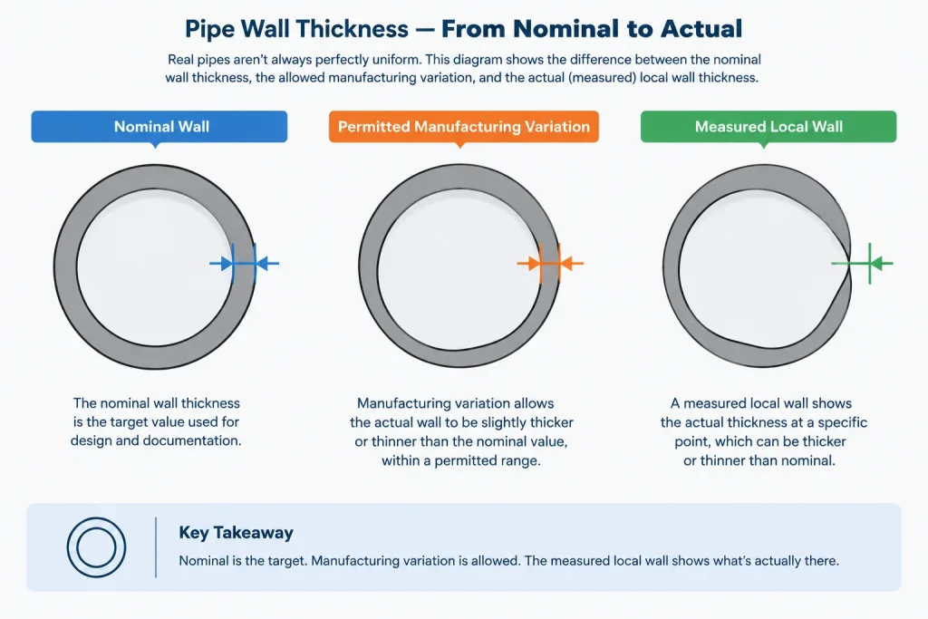
A pipe schedule identifies a nominal wall thickness for a given nominal pipe size, but manufactured pipe is not perfectly uniform. Production methods, dimensional controls, and the applicable product specification may permit the actual wall to vary from its ordered or nominal value. The permitted manufacturing variation is often discussed as pipe mill tolerance.
Mill tolerance matters when engineers verify pressure design, corrosion allowance, mechanical strength, and minimum required wall. It also matters to procurement and inspection because an acceptable delivered pipe may measure differently from the nominal value shown in a dimension table. For CAD users, however, the engineering minimum should not automatically replace the nominal wall in a generic piping model.
The key is to separate three related but different questions: What wall was selected? What minimum wall is required for design? What geometry should the model represent?
What pipe mill tolerance means
Pipe mill tolerance is the manufacturing variation permitted by the applicable product specification. It recognizes that real pipe wall thickness cannot be produced as one exact value at every point along the circumference and length.
The permitted variation is not a universal constant for all piping products. It can depend on the material specification, product form, manufacturing route, size range, ordering basis, and other requirements. Designers should therefore obtain the applicable tolerance from the governing product and project documents rather than applying a remembered percentage to every pipe.
Mill tolerance should also not be confused with measured local thinning caused by corrosion, erosion, grinding, forming, or service damage. Manufacturing acceptance and in-service condition assessment are different activities governed by different criteria.
Nominal wall, required wall, and minimum supplied wall
Several wall-thickness terms may appear in calculations, specifications, inspection reports, and models. They should not be treated as interchangeable.
| Term | Practical meaning | Typical use |
|---|---|---|
| Nominal wall thickness | The stated wall associated with the selected pipe size and schedule or other ordering designation | Dimension references, material selection, catalogs, CAD geometry, and bills of material |
| Required design wall | The wall established by the applicable design calculation before or after specified additions, as defined by the governing design method | Engineering verification |
| Minimum ordered or supplied wall | The lowest acceptable wall under the applicable purchasing basis and permitted manufacturing variation | Procurement and receiving inspection |
| Measured wall | An actual reading at a particular location | Inspection, quality control, and condition assessment |
| Modeled wall | The wall represented by the CAD component | Visualization, interference checking, section views, and data extraction |
A measured value describes only the inspected location and the method used to obtain it. It does not, by itself, redefine the pipe schedule or prove the condition of the full pipe length.
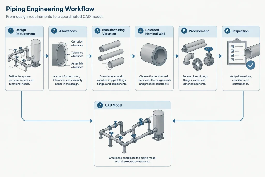
How mill tolerance enters wall-thickness selection
A design calculation may establish a minimum wall needed to resist the applicable design conditions. The engineering workflow may then account for allowances and permitted manufacturing variation according to the governing code, product specification, and project rules. A commercially available nominal wall is selected only after those requirements are understood.
This process is not simply “required wall plus a fixed percentage.” The sequence, variables, and acceptance basis depend on the governing documents. Corrosion allowance, threading or grooving allowance, forming effects, mechanical loads, and other considerations may also influence selection where applicable.
A useful conceptual workflow is:
- Establish the design conditions and applicable piping requirements.
- Calculate the wall needed for the relevant design cases.
- Include required allowances using the project-approved method.
- Account for manufacturing variation under the applicable product specification.
- Select an available pipe wall or schedule that satisfies the complete basis.
- Record the selected commodity and the calculation basis in the controlled engineering documents.
The selected schedule is therefore an outcome of the design and specification process. A CAD user should not independently change it after comparing a dimension table with a calculated minimum.
Why CAD should usually represent nominal geometry
Most plant-layout models use nominal component geometry. Pipe outside diameter is modeled from the applicable dimensional basis, while the bore may be generated from the nominal wall associated with the selected schedule. This produces consistent connections, recognizable section views, and reliable component replacement.
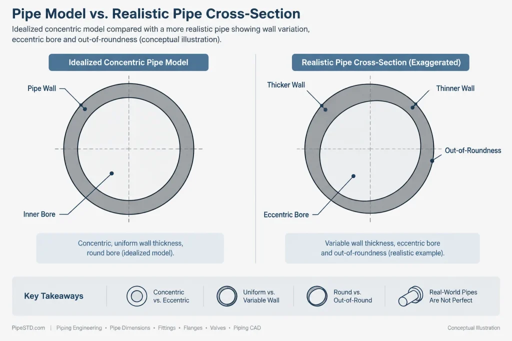
Modeling every pipe at its thinnest permitted manufacturing condition would usually create misleading precision. Actual wall can vary around the circumference and along the length, while a typical CAD pipe is represented as a smooth, concentric cylinder. Changing the entire bore to one minimum value does not realistically reproduce manufacturing variation.
Using minimum wall as ordinary model geometry can also create avoidable data problems:
- The modeled bore may no longer match standard nominal component records.
- Section views may imply a specially machined or controlled inside diameter.
- Automated material reports may no longer correspond to the selected schedule.
- Connections to fittings, valves, and flanges may appear inconsistent.
- Calculated model volume and weight may be mistaken for guaranteed supplied values.
For these reasons, nominal geometry is normally the clearer default for a reusable piping library. Design minimums and procurement tolerances belong in controlled properties, calculations, specifications, or notes unless the project requires another modeling convention.
Cases where the actual bore needs closer attention
Nominal geometry is not adequate for every task. The actual or guaranteed bore may become important when a component passes through the pipe, when internal alignment is critical, or when a process calculation depends on a tightly controlled flow area.
Examples can include piggable systems, internally lined piping, close-fitting inserts, specialty meters, machined transition pieces, and connections where internal mismatch is specifically limited. These cases require verified project or manufacturer information. A generic schedule-based model should not be assumed to represent the worst-case or guaranteed bore.
If bore control affects layout or fabrication, the model should distinguish between reference geometry and verified interface geometry. The relevant requirement should also appear in the purchasing and fabrication documentation; a detailed CAD bore alone does not create a manufacturing requirement.
Mill tolerance is not corrosion allowance
Mill tolerance and corrosion allowance address different issues. Mill tolerance covers permitted variation in the new manufactured product. Corrosion allowance is a design provision for expected material loss during service, where required by the design basis.
One should not be used as a substitute for the other. A nominal wall selection may need to accommodate both, but they enter the engineering process for different reasons. Likewise, a pipe delivered near its permitted minimum wall has not necessarily consumed the corrosion allowance. Acceptance depends on how the design calculation and purchasing requirements were established.
Mill tolerance is not the same as ovality or eccentricity
Wall variation can be related to other geometric characteristics, but the terms describe different measurements:
- Wall-thickness variation concerns the distance between the outside and inside surfaces.
- Ovality or out-of-roundness concerns variation in diameter around a cross-section.
- Eccentricity concerns offset between the centers of the inside and outside surfaces.
- Outside-diameter tolerance concerns permitted variation of the external diameter.
A pipe can satisfy one dimensional limit while another characteristic still requires evaluation. CAD models commonly idealize all four conditions by using concentric circular cylinders. That simplification is useful for layout, but it should not be mistaken for an inspection model.
Recommended CAD and documentation workflow
1. Keep the component identity explicit
Store nominal pipe size, schedule or wall designation, material specification, and applicable piping class as separate properties. Do not rely on modeled inside diameter as the only identifier.
2. Use nominal library geometry
Build reusable pipe components from verified nominal dimension data. If wall thickness is not needed for the model’s purpose, a centerline or outside-envelope representation may be more appropriate than a detailed hollow solid.
3. Carry engineering minimums as data
Where minimum wall is relevant to design review, place it in an approved calculation, line-class record, specification field, or other controlled dataset. Label the basis clearly so users do not confuse calculated, ordered, and measured values.
4. Flag bore-critical interfaces
Use a note, model status, interface object, or hold point when the actual bore must be confirmed. Replace assumed geometry with verified vendor, fabrication, or inspection data when it becomes available.
5. Avoid false manufacturing detail
Do not model arbitrary local wall variation merely to make the pipe look realistic. Unless inspection data are being reconstructed for a specific purpose, such detail adds complexity without creating reliable engineering information.
A practical review question
When wall values differ between a calculation, pipe table, CAD model, and inspection report, do not ask only, “Which number is correct?” Ask what each number represents. One may be a required design minimum, another a nominal ordered wall, another an idealized model value, and another a local field measurement.
Pipe mill tolerance is best managed by preserving those distinctions. Engineering establishes the required and selected wall, procurement defines the acceptable supplied product, inspection verifies what was received or remains in service, and CAD represents the geometry appropriate to its intended use.
Choosing the controlling value for each task
No single wall-thickness value should control every piping activity. The appropriate value depends on the decision being made and the document authorized to support that decision.
- Design verification: Use the governing calculation basis, including applicable allowances and manufacturing variation.
- Commodity selection: Use the approved nominal wall or schedule associated with the selected pipe item.
- Purchasing: Use the material specification, ordering requirements, and project acceptance criteria.
- Receiving inspection: Compare measured results with the applicable purchasing basis rather than with CAD geometry alone.
- Plant layout: Use the project-approved nominal or simplified library representation.
- Bore-critical interfaces: Use verified interface requirements and manufacturer, fabrication, or inspection information as applicable.
- Condition assessment: Use qualified measurements and the approved assessment method; do not infer remaining wall from a generic model.
Data checks before issuing a piping model
A useful model review confirms that the component identity and geometry basis remain traceable. Reviewers should be able to determine whether a wall value is nominal, calculated, ordered, guaranteed, or measured without reverse-engineering it from the solid model.
- Confirm that the pipe size and wall or schedule designation agree with the approved piping class.
- Confirm that model properties do not describe nominal geometry as a guaranteed minimum bore.
- Keep calculated minimum wall separate from the commodity identifier.
- Identify interfaces where internal clearance depends on verified bore information.
- Check whether extracted volume or weight is being treated as an estimate or as controlled purchasing data.
- Record the source and status of any geometry that replaces the standard library representation.
This separation supports cleaner revisions. An engineering calculation can change without silently redefining library geometry, and verified manufacturer data can update a critical interface without changing every generic pipe component.
Frequently asked questions
Should minimum design wall be used as the wall in a CAD pipe model?
Not automatically. Minimum design wall supports engineering verification, while a reusable CAD component generally represents the approved nominal pipe item. Use another geometry basis only when the project requires it and the basis is clearly documented.
Does a pipe schedule guarantee one exact inside diameter?
No. Schedule-based references identify nominal wall information, while permitted manufacturing variation and other geometric characteristics can affect the actual bore. Obtain verified information when internal clearance is critical.
Can an inspection reading replace the nominal wall in the model?
A local reading should not normally redefine the complete modeled pipe. It represents a measurement at a particular location and must be interpreted using the inspection method, coverage, and applicable acceptance criteria.
Should corrosion allowance be shown as a separate CAD layer or solid?
Usually it is more useful as controlled engineering data than as separate physical geometry. A project may adopt a special visualization convention, but that convention should not imply that corrosion occurs uniformly or creates a guaranteed future bore.
Can model-derived weight be used for purchasing or support design?
Only when the geometry, material data, calculation method, and intended use have been verified. A weight extracted from idealized nominal geometry should not be presented as a guaranteed supplied value.
What should be done when actual bore controls an interface?
Flag the interface, define the required clearance or alignment basis in controlled documentation, and obtain verified manufacturer, fabrication, or inspection data. Detailed CAD geometry alone does not impose a purchasing or manufacturing requirement.