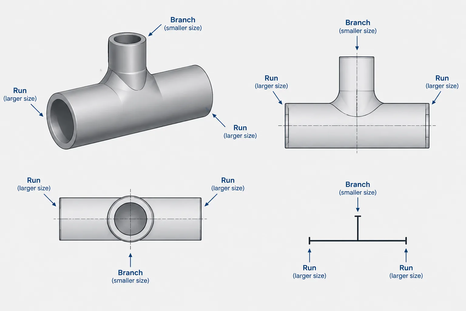
Reading a reducing tee description requires more than identifying a large size and a small size. The notation must be tied to the fitting’s physical ports, the catalog’s ordering convention, and the way the CAD system stores connection data.
This guide explains how to distinguish the straight-through run from the branch, interpret abbreviated size descriptions, and verify that catalog records, model ports, drawings, and material lists all describe the same component.
A reducing tee connects three pipe runs while changing nominal size at one or more ports. The concept appears simple, but reducing tee size notation can cause mistakes when a catalog description, piping specification, bill of materials, and CAD component use different port orders.
The main difficulty is that a series of size designations does not explain itself. A designer must know which values describe the straight-through run, which value belongs to the branch, and whether the source has abbreviated two equal run sizes. Correct interpretation affects component selection, fitting orientation, pipe cut lengths, material quantities, and model connectivity.
The three ports of a reducing tee
A tee has two ports on a common centerline and a third port branching from that line. The aligned ports form the run. The perpendicular or angled port is the branch or outlet, depending on the terminology used by the catalog or project.
For a typical reducing tee, the two run ports have the same nominal size and the branch is smaller. A useful symbolic description is:
- A: first run port
- A: second run port
- B: branch port
This arrangement may be written as A × A × B. Some sources shorten it to A × B because the equal run ends are understood. That shortened form is convenient, but it should not be assumed to be universal.
Straight tees and reducing tees
A straight tee, sometimes called an equal tee, has the same nominal size at all three ports. A reducing tee has a size change at the branch or, in less typical configurations, another unequal-port arrangement.
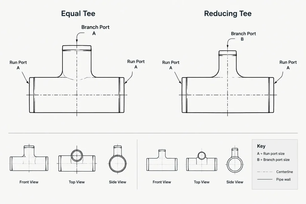
| Component description | Port relationship | Key interpretation issue |
|---|---|---|
| Straight or equal tee | Both run ports and the branch are the same nominal size | Orientation does not change the nominal port sizes |
| Reducing tee | The branch is commonly smaller than the equal run ports | The branch value must be mapped to the correct CAD port |
| Special unequal-port tee | Ports may not follow the usual equal-run pattern | Each connection must be identified explicitly |
| Fabricated branch assembly | Geometry and sizes are defined by the fabrication design | Do not treat it automatically as a catalog reducing tee |
A tee with a smaller branch should also not be confused with a straight tee followed by a separate reducer. Those arrangements may connect the same nominal line sizes, but they do not have the same geometry, component count, weld locations, takeoff dimensions, or material description.
Why size order cannot be guessed
Many piping catalogs list tee sizes in a run-by-run-by-branch sequence. However, project databases, vendor descriptions, procurement systems, and legacy drawings may use abbreviated or customized formats. A two-value description may mean run size by branch size, but that meaning should be confirmed from the source.
There is additional risk when text is separated from graphics. In a catalog table, column headings may make the port order obvious. After the same description is copied into a spreadsheet or material list, that context can disappear. A string of nominal sizes then becomes ambiguous.
When reading reducing tee size notation, check:
- Whether all three ports are listed or the equal run size is abbreviated
- Whether the source defines the order as run, run, branch
- Whether the term outlet means the branch port
- Whether the item is a standard fitting, a branch outlet fitting, or a fabricated assembly
- Whether nominal size is being confused with an actual bore or end dimension
- Whether the description includes reducing ends that require separate identification
If the notation remains unclear, the fitting sketch, port labels, manufacturer data, or approved project catalog should control the interpretation. Visual similarity alone is not enough.
Nominal size does not define the complete fitting
A reducing tee size description identifies nominal connection sizes, not every property needed to select or model the component. Two items with matching port sizes may differ in material, wall designation, end preparation, dimensional basis, manufacturing form, or project commodity code.
The fitting record may also need to distinguish butt-weld, socket-weld, threaded, or another connection type. These end connections affect the component geometry and the way adjoining pipe is located. A nominal port mapping therefore cannot replace the complete piping specification.
Likewise, the size notation does not provide center-to-end dimensions. Those dimensions must come from the applicable verified dimensional source or approved manufacturer information. Designers should not derive a reducing tee’s takeoff by scaling a different tee or by assuming that its branch takeoff matches another configuration.
Mapping reducing tees in a CAD catalog
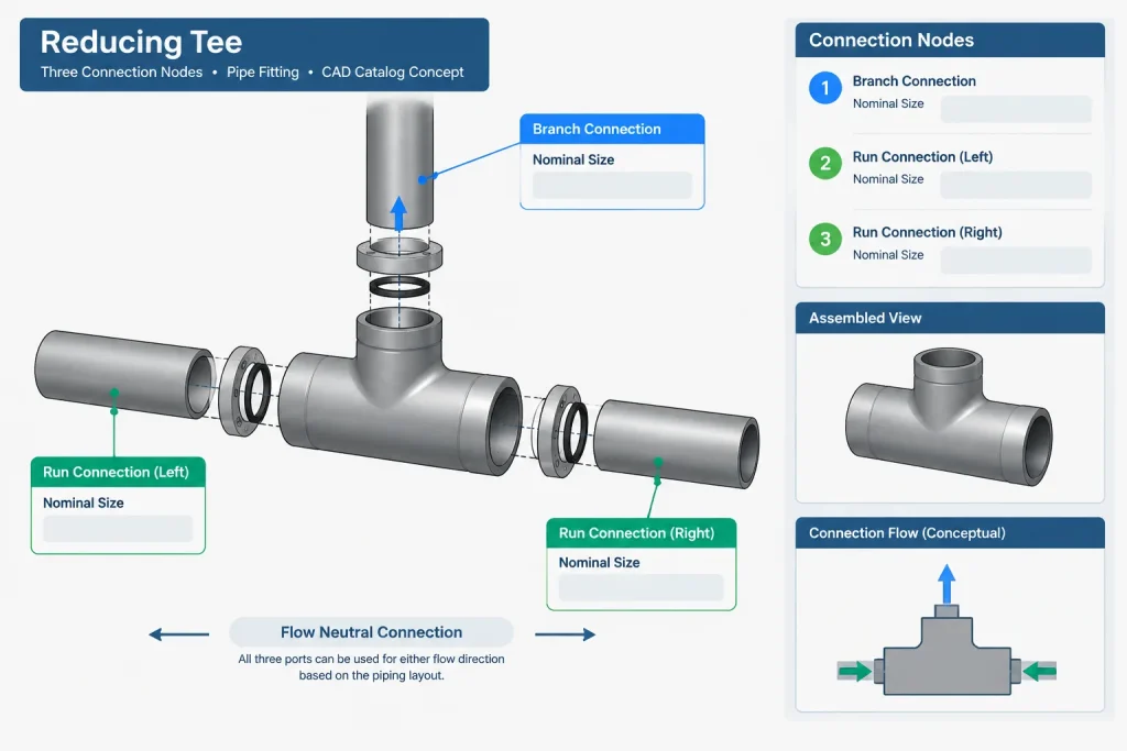
CAD systems commonly treat a tee as a component with three connection ports. Each port may store nominal size, end type, direction, connection coordinate, and specification data. The port names used by the software may be descriptive, sequential, or hidden from the user.
A robust catalog workflow maps the physical fitting deliberately:
- Identify the two collinear ports. These form the run regardless of how the model is rotated.
- Identify the branch port. This is the connection leaving the run centerline.
- Assign nominal sizes by port. Do not rely only on a combined text description.
- Verify connection types. The adjoining pipe and fitting ends must represent the intended joint.
- Confirm connection coordinates. The modeled center-to-end locations must match the verified component record.
- Test rotation and placement. Rotating the tee should change its orientation in space, not swap its stored run and branch identities.
- Review generated output. Check the isometric, material list, and connection report rather than inspecting only the three-dimensional shape.
A common modeling failure occurs when the smaller port is geometrically placed on the branch but internally labeled as a run port. The model may look correct while reports or automated connections are wrong. Port-level validation catches this problem.
Use explicit port fields
Where the catalog structure allows it, separate fields such as run end one, run end two, and branch are safer than a single size string. The formatted description can then be generated from controlled data rather than serving as the only record of port sizes.
For equal-run reducing tees, a catalog may store the repeated run size twice even if the displayed description shows it once. This supports connectivity checks and reduces dependence on shorthand notation.
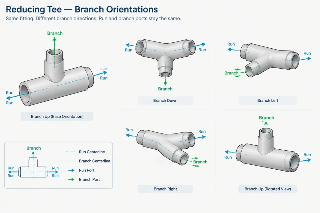
Orientation is different from port identity
A reducing tee can be rolled around the run centerline so the branch points up, down, sideways, or at another modeled angle. This changes branch orientation but does not change which ports form the run.
That distinction is important in isometrics and orthographic drawings. The page direction of the branch is not a reliable clue to size order. A branch shown vertically on one drawing may appear diagonal on an isometric or point toward the viewer in another projection.
Use centerlines, connectivity, and component data to identify the ports. Do not infer run and branch solely from how the symbol is drawn on the sheet.
Material list and procurement checks
A material description should communicate enough information to identify the intended tee without forcing the purchaser to interpret an undocumented convention. The exact format depends on the project, but the controlled data generally needs to address:
- Component type
- Run and branch nominal sizes
- End connection or fitting form
- Material and applicable project specification
- Wall or class designation where relevant
- Commodity code or catalog identifier
Before issuing a bill of materials, compare the description with the CAD port data. Also check that the quantity has not been split between multiple text descriptions representing the same item. Conversely, similar-looking descriptions should not be merged if their material, end type, wall designation, or dimensional source differs.
A practical review checklist
- Confirm which two ports form the straight-through run.
- Confirm which port is the branch or outlet.
- Determine whether the notation lists all ports or abbreviates equal run ends.
- Verify that the smaller nominal size is assigned to the intended physical port.
- Check the fitting type and end connections against the piping specification.
- Use verified dimensional data rather than scaled geometry.
- Inspect CAD port properties, not just the displayed solid.
- Compare model data with the isometric and material description.
- Clarify any nonstandard unequal-port arrangement with an explicit sketch or port schedule.
Key takeaway
Reducing tee size notation is fundamentally a port-mapping problem. The designer must distinguish the two run connections from the branch, understand whether repeated sizes have been abbreviated, and connect the notation to verified component data. Treating a size string as self-explanatory can produce errors even when the CAD geometry looks correct. Explicit port assignments, controlled descriptions, and cross-checks between the specification, model, drawing, and material list provide a more reliable workflow.
Build a traceable port-mapping workflow
A reliable reducing tee record should allow another user to follow each nominal size from the source catalog to the corresponding CAD port and then into project output. This traceability is more dependable than treating the displayed component description as the controlling data.
Start with an approved fitting sketch or catalog definition and identify the physical role of every connection. Record the two aligned connections as run ports and the remaining connection as the branch. Then compare those roles with the CAD port names, connection directions, nominal-size fields, and end types.
Keep source notation separate from normalized data
A catalog description can be retained exactly as published while the project database stores each port in a separate controlled field. This avoids changing the source wording and still gives designers, reports, and connectivity tools an unambiguous port map.
If a source abbreviates the repeated run size, the normalized record should not depend on that abbreviation. Each CAD connection should carry the data required for validation, while the human-readable description can follow the approved project format.
Manage exceptions explicitly
Unusual unequal-port tees, fabricated branches, and records with unclear ordering should be treated as exceptions rather than forced into the common reducing-tee pattern. Flag the ambiguity, attach an identifying sketch or port schedule, and obtain confirmation from the controlling project or manufacturer information.
Check data at handoff points
Errors often become visible when data moves between systems. Review the port mapping when a catalog item is imported, when a model component is placed, when an isometric is generated, and when a material list is issued. The component description, graphical orientation, and stored port properties should agree without relying on an undocumented size-order convention.
Frequently asked questions
Which connection is the run on a reducing tee?
The run consists of the two ports sharing the straight centerline through the tee. The branch is the connection leaving that centerline. Model rotation does not change these identities.
Does a two-value tee description always mean run size by branch size?
No. That format commonly abbreviates equal run ends, but its meaning must be confirmed from the catalog headings, project convention, fitting sketch, or controlled database definition.
Can the smallest port automatically be treated as the branch?
Not safely. It may be the branch in a typical reducing tee, but special unequal-port configurations can follow a different arrangement. Physical port roles should be verified rather than inferred only from relative size.
Why can a reducing tee look correct in CAD but still be wrong?
The solid geometry may place the smaller connection in the expected location while the underlying port fields assign it a run identity. That mismatch can affect connectivity, reports, isometrics, and material descriptions.
Is nominal size enough to select a reducing tee?
No. Nominal port sizes do not define the complete component. Selection also depends on the applicable piping specification, material, fitting form, end connections, wall or class designation where relevant, and verified dimensional data.
Should center-to-end dimensions be inferred from the model shape?
No. Connection coordinates and takeoff dimensions should come from an approved dimensional source or verified manufacturer information, not from visual scaling or assumptions based on another fitting.